PIC18F4550 PWM
Pulse Width Modulation (PWM) is a technique by which the width of a pulse is varied while keeping the frequency constant. PWM is generally used to control the speed of the DC motors or servo motors.
Introduction
Pulse Width Modulation (PWM) is a technique by which the width of a pulse is varied while keeping the frequency of the wave constant.

A period of a pulse consists of an ON cycle (5V) and an OFF cycle (0V). The fraction for which the signal is ON over a period is known as a duty cycle.
E.g. A pulse with a period of 10ms will remain ON (high) for 2ms.Therefore, the duty cycle will be
D = 2ms / 10ms = 20%
Through the PWM technique, we can control the power delivered to the load by using the ON-OFF signal. The PWM signals can be used to control the speed of DC motors and to change the intensity of the LED. Moreover, it can also be used to generate sine signals.
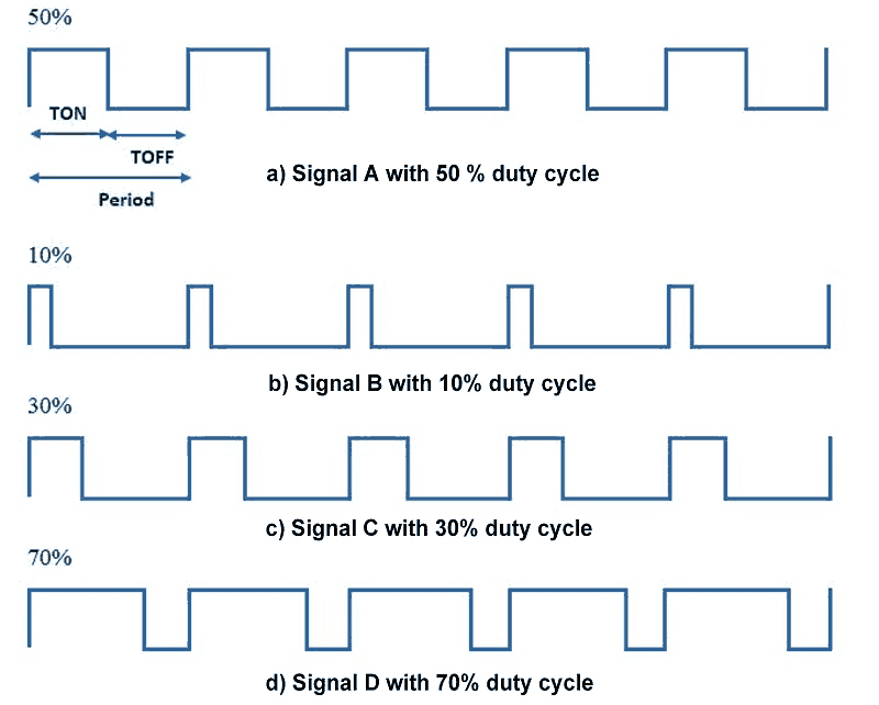
Pulse Width Modulated signals with different duty cycle are shown below
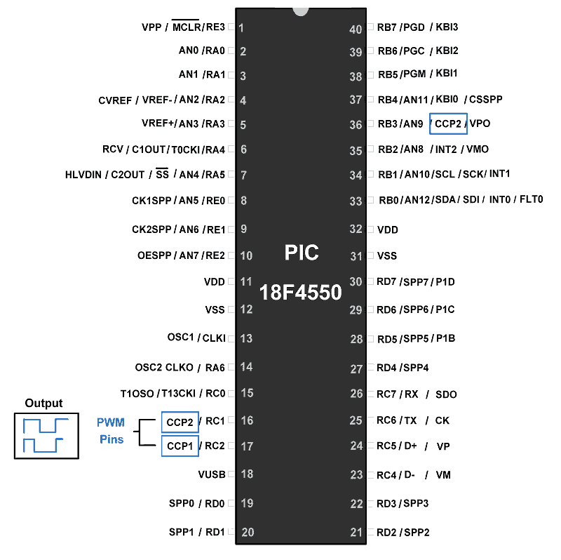
PIC18F4550 controller has an in-built 10-bit PWM module known as the CCP module. The pin CCP1 (RC2) is used for generating PWM signals. It needs to be configured as an output.
PIC18F4550 PWM Pins
In PIC18F4550, only Timer2 can be used for PWM generation. TMR2 is a 16-bit Timer2 register which is used to hold the count.
In PIC18F4550 following registers are used for PWM generation.
Note: Here, we are using a CCP1 module. If we want to use the CCP2 module then we need to modify the register name as CCPR1L to CCPR2L, CCP1CON to CCP2CON.
Also, make the RC1 pin as output for PWM generation.
CCPR1H and CCPR1L register
In the CCP module, there is a 16-bit register which is split into two 8-bit registers - CCPR1H and CCPR1L.
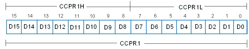
- Only CCPR1L is used to decide the duty cycle of the PWM. CCPR1H is not user-accessible for the PWM mode.
- As the PIC18F4550 generates a 10-bit PWM pulse, to set the duty cycle it uses a 10-bit register. The higher 8 bits (MSBs) DC1B9: DC1B2 of this register are in CCPR1L register (8-bit) and lower 2 bits(LSBs) DC1B1: DC1B0, which are used for a decimal portion in duty cycle, are in CCP1CON register at bit 5 and 4 respectively.
- So the 10-bit value for duty cycle is represented by CCPR1L: CCP1CON<5: 4>
PR2 register
- It is an 8-bit register that is used to load a count for a period of the pulse (TPWM).
Working of PWM in CCP module
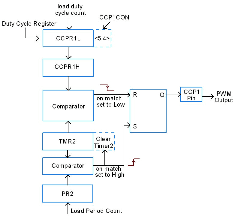
- Load the period value in a PR2 register and the duty cycle value in CCPR1L: CCP1CON<5: 4> registers and initialize the CCP1 pin as an output.
- Configure the T2CON register and set the TMR2 register to 0. Also, start the Timer2.
- Now when a match occurs between registers PR2 and TMR2, pin CCP1 is pulled high and TMR2 is cleared.
- The value of CCPR1L along with the CCP1CON<5: 4> which is a count for duty cycle is moved to the CCPR1H.
- Finally, TMR2 is compared with the CCPR1H along with two lower bits of a duty cycle. When matched, the pin CCP1goes low.
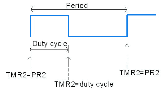
This is how PWM is generated in PIC18F4550.
CCP1CON register: CCP1 Control Register for PWM

DC1B1: DC1B0
These two bits are LSBs which are used for defining the decimal value of a duty cycle.
CCP1M3: CCP1M0: CCP1 module mode select bits
11xx = PWM mode
Other combinations are used to capture and compare modes.
Calculations
Now how to set value for the PR2 register which defines the period value of a pulse.
where,
Fpwm – Frequency of PWM signal
Now, let us see how to set a value for the CCPR1L which decides the duty cycle of a pulse. We know that a duty cycle is some % of the PR2 (period) register. For example, if PR2 is 199 then a 20% duty cycle of the 199 is given by,

e.g.
(CCPR1L: CCP1CON<5: 4>) = (199 + 1) x (20/100)
(CCPR1L: CCP1CON<5: 4>) = 40 = 0b0010100000
So, load MSB 8-bits of the above result to the CCPR1L and 2 LSB bits in CCP1CON <5:4>.
i.e. CCPR1L = 0b00101000 = 0x28
CCP1CON <5:4> = 0b00
Note: CCPR1L (duty cycle) value should be always less than or equal to the PR2 (period) value. If the CCPR1L value is greater than the PR2 value, the pin CCP1 will not be cleared. This allows a duty cycle of 100% and gives the output.
Note: But, if a PR2 value is exceeding 8-bit value i.e. 255 then we have to increase Timer2 pre-scale value.
Max PWM Resolution
bits
The PWM duty cycle must be a value between 0 and (2 ^ PWM Resolution) - 1.
Steps for Programming
- Load the PR2 value which will decide the period of the pulse.
- Set the duty cycle by loading value in the CCPR1L: CCP1CON<5: 4>
- Configure the CCP1CON register for setting a PWM mode.
- Initialize the pin CCP1as an output pin which will give PWM output.
- Configure the T2CON register and enable TMR2 using T2CON
Application 1
Let us generate 10KHz PWM with a 20% duty cycle.
/*
   Generating 10KHz PWM with 20% duty cycle
   www.electronicwings.com
*/

#include "osc_config.h"
#include <pic18f4550.h>

void main()
{

    OSCCON = 0x72;	/* Set internal clock to 8MHz */
    TRISC2 = 0;		/* Set CCP1 pin as output for PWM out */
    PR2 = 199;		/* Load period value */
    CCPR1L = 40;	/* load duty cycle value */
    T2CON = 0;		/* No pre-scalar, timer2 is off */
    CCP1CON = 0x0C;	/* Set PWM mode and no decimal for PWM */
    TMR2 = 0;		/* Clear Timer2 initially */
    TMR2ON = 1;		/* Timer ON for start counting*/

    while(1);

}
Application 2
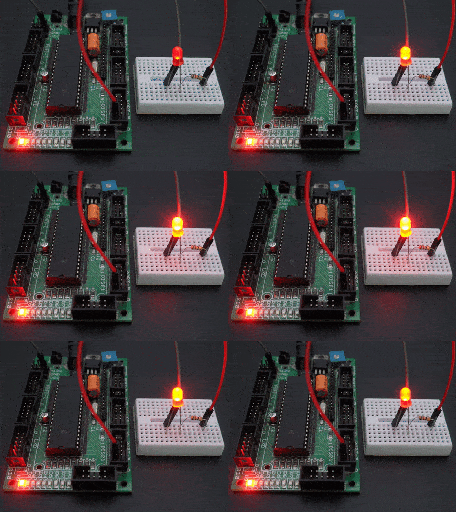
Now, let us control the intensity of LED by generating PWM with different duty cycles using PIC18F4550.
/*
* Control intensity of LED using PIC18F4550
* www.electronicwings.com
*/

#include "osc_config.h"
#include <p18f4550.h>

void MSdelay(unsigned int);

void main()
{
    unsigned int duty_cycle;
    OSCCON=0x72;         /* set internal clock to 8MHz */
    TRISCbits.TRISC2=0;  /* Set CCP1 pin as output for PWM out */
    PR2=199;             /* load period value in PR2 register */
    CCPR1L=1;            /* load duty cycle */
    T2CON=0;             /* no pre-scalar,timer2 is off */
    CCP1CON=0x0C;        /* set PWM mode and no decimal value for PWM */
    TMR2=0;
    T2CONbits.TMR2ON=1;  /* Turn ON Timer2 */
    while(1)
    {

        for(duty_cycle=1;duty_cycle<199;duty_cycle++)
        {
            CCPR1L = duty_cycle;   /* load duty cycle */
            MSdelay(20);
        }
        MSdelay(500);

        for(duty_cycle=199;duty_cycle>1;duty_cycle--)
        {
            CCPR1L = duty_cycle;   /* load duty cycle */
            MSdelay(20);
        }
        MSdelay(500);
    }

}

void MSdelay(unsigned int val)
{
     unsigned int i,j;
        for(i=0;i<=val;i++)
            for(j=0;j<165;j++);      /*This count Provide delay of 1 ms for 8MHz Frequency */
 }
Video
Generate Two different PWM simultaneously
- We can generate two different PWM on PIC18F4550 on two different channels i.e. CCP1 and CCP2.
- But these generated PWMs will be of the same frequency. This is because to generate PWM, only Timer 2 is used which is common for both the CCP1 and CCP2.
- So, the period count which is loaded in the PR2 register to compare it with the Timer 2 (TMR2) register is shared/common. Thus, we can generate two PWM with different duty cycle but with the same frequency.
Now, we will generate Two different PWM on CCP1(RC2) & CCP2(RC1) having the same frequency.
Here, CCP1 will generate PWM of 25% Duty Cycle whereas CCP2 will generate PWM of 50% Duty Cycle.
/*
* Generate Two PWM with different duty cycle on PIC18F4550
* www.electronicwings.com
*/
#include <xc.h>
#include "configuration_bit_header.h"

void main()
{
    OSCCON = 0x76;	/* Set internal clock to 8MHz */
    TRISC1 = 0;		/* Set CCP2 pin as output for PWM out */
    TRISC2 = 0;		/* Set CCP1 pin as output for PWM out */
    PR2 = 199;		/* Load period value */

    /**** generate PWM on CCP1 ****/
    CCP1CON = 0x0C;	/* Set PWM mode and no decimal for PWM */
    CCPR1L = 50;    /* load 25% duty cycle value */

    /**** generate PWM on CCP2 ****/
    CCP2CON = 0x0C;	/* Set PWM mode and no decimal for PWM */
    CCPR2L = 100;	/* load 50% duty cycle value */

    /*configure Timer 2 for PWM*/
    T2CON = 0;		/* No pre-scalar, timer2 is off */
    TMR2 = 0;		/* Clear Timer2 initially */
    TMR2ON = 1;		/* Timer ON for start counting*/
    while(1);
}
Components Used
Powered by
Downloads
Comments23
Join the discussion — share a question or tip.
- LE
Hello Can this chip (PIC18F4550) control many servo motors (12 items), simultaneously? servo motor - mg995 I want to make servo controller 12ch using pic18f4550.
- JE
Please why did you not use delay_ms(1) in the second example??
- GE
hi i am doing a similar project, i need to make an ADC with PWM: The problem to be solved will be that with the use of the PWM of the microcontroller an analog signal will be read that can vary from zero to five volts, and it will reflect the duty cycle of the output, if it has 2.5 volts it will be 50% of the duty cycle , of a signal that has a frequency of 20 khz.
- SR
I need to synch the pwm out with the other out pin of pic 18f4550. Is it possible to sychronize the outputs.Kindly help
- VI
can i get variable pwm according to temperature? i mean if temperature increases the pulse width should increase such that the speed of a motor increases and also for decreasing. suggest me how to code. and does the application 2 helps me? thanks in advance
- DO
can this code be used for pic18f4520?
- KH
The PIC18F4550 has two PWMs i.e. CCP1 and CCP2, i want toggle ccp2. means CCP1 is inverse of CCP2 within same frequency. how can i do this . please sir tell me Khalil Javed
- TY
Hi there, Why do you use CCP1CON<5:4> like that? I mean, the datasheet only says those are the 2 LSBs, so if you want to load 40 dec on those 10 bits, wouldn't it be 0x09 on CCPR1L and 0b00 on CCP1CON<5:4>? I haven't been able to test this so I'm really not getting it. You just load 40dec on CCPR1L register and that's it :S
- IS
Hi I wish to use pic18f4550 to generate two different pwm frequencies at ccp1 and ccp2 to control two different motors. Can I do this? Also when using setPeriod() are you changing the internal oscillator frequency (say 8mhz) to a different rate. How does that affect other stuff the chip is controlling? Thanks Ian
- MOmohanraj· edited
Hey am doing similar project i want to vary the PWM frequency by using adc is this possible do it ?? If it so let me know as soon as possible Details of project : I have an input adc once the adc value is changed the PWM frequency and duty cycles are should changed according to that my frequency vary from 10Khz to 100Khz. And also i need two PWM signals ( Enhanced Capture PWM Half bridge mode)
- LOlokeshc· edited
hello mohanraj, it is possible to use ADC value for varying duty cycle and frequency of PWM. To do this you can refer following link, http://www.electronicwings.com/pic/servo-motor-interfacing-with-pic18f4550 It uses ADC to change duty cycle for rotating servo motor. It will surely be helpful for you to build an application.
- LOlokeshc· edited
Replying to @mohanraj
You can vary PWM frequency too. Just you need to create function for generating pwm of specific frequency with specific duty cycle. For specific duty cycle I provided you link which can be useful for you. For specific frequency function, you need to reconfigure pwm register as per your need. For two pwm signal, register configurations may be almost same. For this you can refer Application notes by Microchip.
- LOlokeshc· edited
Hi rodch98, Do you need to vary PWM duty cycle from 0 to 100 %? If yes then you need to make changes in given 2nd example. you have to change for loop as follows, for(duty_cycle=0;duty_cycle&lt;199;duty_cycle+5) The variable looking duty_cycle is 199 for 100 % duty cycle. It may work for you. Or you can use function for variable duty cycle used in the following link, http://www.electronicwings.com/pic/servo-motor-interfacing-with-pic18f4550