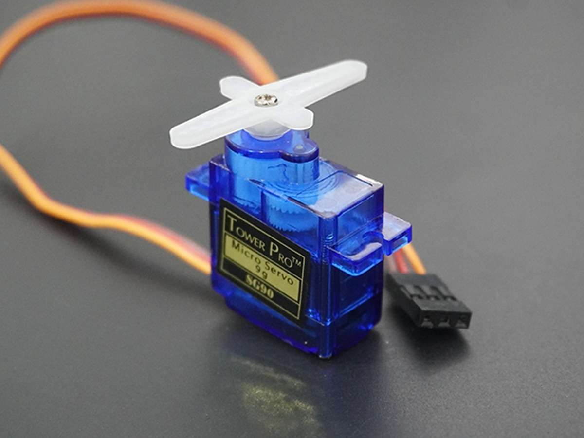
Servo Motor Interfacing with PIC18F4550
Servo motor is an electromechanical device that consists of a Motor, Gear assembly, and feedback circuitry. It is used in Robotics applications, airplanes, rudders, quadcopters, etc.
Overview of Servo Motor
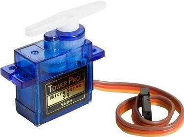
A servo motor is an electric device used for precise control of angular rotation. It is used where precise control is required, like in the case of control of the robotic arm.
- It consists of a suitable motor with control circuitry for precise position control of the motor shaft.
- It is a closed-loop system.
- The rotation angle of the servo motor is controlled by applying a PWM signal to it.
- By varying the width of the PWM signal, we can change the rotation angle and direction of the motor.
For more information about Servo Motor and how to use it, refer to the topic Servo Motor in the sensors and modules section.
Generating PWM using PIC18F4550
SG90 servo has a practical duty cycle time for -90° to +90 rotation that is different from ideal.
At ~0.6ms (3% duty cycle) we get shaft position at -90° of its rotation.
At ~1.4ms (7% duty cycle) we get shaft position at 0° (neutral) of its rotation.
At ~2.4ms (12% duty cycle) we get shaft position at +90° of its rotation.
To control servo motor in between -90° to +90° rotation. We need to generate a PWM waveform of 50Hz with duty cycle variation from ~0.6ms to ~2.4ms. We can use a fast PWM mode of PIC18F4550 using Timer1.
For more information about generating PWM in PIC18F4550 and how to use it, refer to PIC18F4550 PWM.
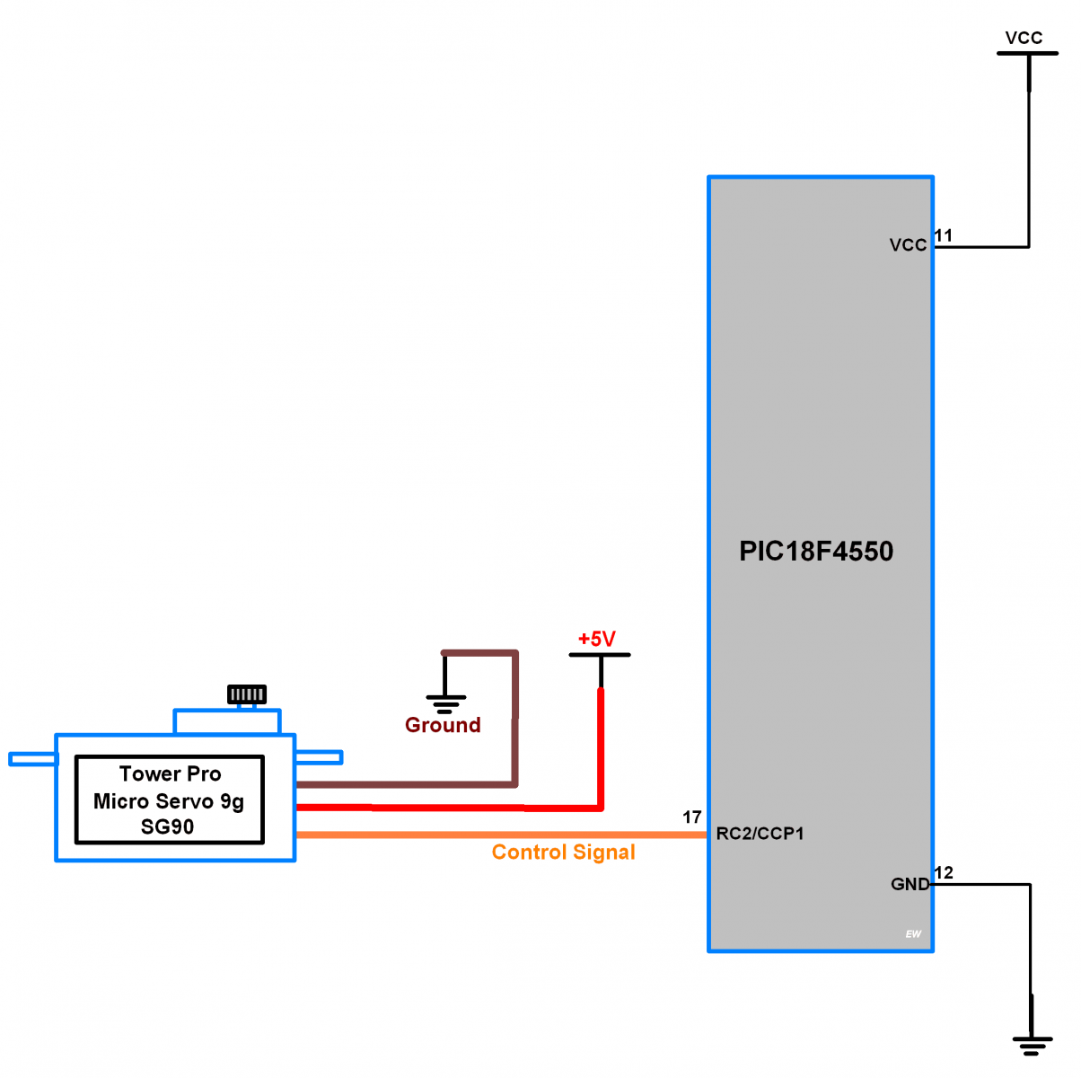
Connection Diagram of Servo Motor to PIC18F4550
Servo Motor Example using PIC18F4550
Now let’s program PIC18F4550 to generate 50Hz PWM to control Servo Motor in an angle between -90° to +90° rotation.
Servo Motor Code for PIC18F4550
/*
 * Servo control using PIC
 * http://www.electronicwings.com
 */

#include <pic18f4550.h>
#include <stdio.h>
#include <math.h>
#include "Configuration_header_file.h"

#define MINTHR              8000
#define RESOLUTION          488

#define InternalOsc_8MHz    8000000
#define InternalOsc_4MHz    4000000
#define InternalOsc_2MHz    2000000
#define InternalOsc_1MHz    1000000
#define InternalOsc_500KHz  500000
#define InternalOsc_250KHz  250000
#define InternalOsc_125KHz  125000
#define InternalOsc_31KHz   31000

#define Timer2Prescale_1    1
#define Timer2Prescale_4    4
#define Timer2Prescale_16   16

void PWM_Init()            /* Initialize PWM */
{
    TRISCbits.TRISC2 = 0;  /* Set CCP1 pin as output for PWM out */
    CCP1CON = 0x0C;        /* Set PWM mode */
}

int setPeriodTo(unsigned long FPWM)/* Set period */
{
    int clockSelectBits, TimerPrescaleBits;
    int TimerPrescaleValue;
    float period;
    unsigned long FOSC, _resolution = RESOLUTION;

    if (FPWM < MINTHR)    {TimerPrescaleBits = 2; TimerPrescaleValue = Timer2Prescale_16;}
    else                  {TimerPrescaleBits = 0; TimerPrescaleValue = Timer2Prescale_1;}

    if (FPWM > _resolution)               {clockSelectBits = 7; FOSC = InternalOsc_8MHz;}
    else if (FPWM > (_resolution >>= 1))  {clockSelectBits = 6; FOSC = InternalOsc_4MHz;}
    else if (FPWM > (_resolution >>= 1))  {clockSelectBits = 5; FOSC = InternalOsc_2MHz;}
    else if (FPWM > (_resolution >>= 1))  {clockSelectBits = 4; FOSC = InternalOsc_1MHz;}
    else if (FPWM > (_resolution >>= 1))  {clockSelectBits = 3; FOSC = InternalOsc_500KHz;}
    else if (FPWM > (_resolution >>= 1))  {clockSelectBits = 2; FOSC = InternalOsc_250KHz;}
    else if (FPWM > (_resolution >>= 1))  {clockSelectBits = 1; FOSC = InternalOsc_125KHz;}
    else                                  {clockSelectBits = 0; FOSC = InternalOsc_31KHz;}

    period = ((float)FOSC / (4.0 * (float)TimerPrescaleValue * (float)FPWM)) - 1.0;
    period = round(period);

    OSCCON = ((clockSelectBits & 0x07) << 4) | 0x02;
    PR2 = (int)period;
    T2CON = TimerPrescaleBits;
    TMR2 = 0;
    T2CONbits.TMR2ON = 1;  /* Turn ON Timer2 */
    return (int)period;
}

void SetDutyCycleTo(float Duty_cycle, int Period)
{
    int PWM10BitValue;

    PWM10BitValue = 4.0 * ((float)Period + 1.0) * (Duty_cycle/100.0);
    CCPR1L = (PWM10BitValue >> 2);
    CCP1CON = ((PWM10BitValue & 0x03) << 4) | 0x0C;
}


void delay(unsigned int val)
{
     unsigned int i,j;
        for(i=0;i<val;i++)
            for(j=0;j<10;j++);
}

int main()
{
    int Period;
    PWM_Init();                 /* Initialize PWM */
    Period = setPeriodTo(50);   /* 50Hz PWM frequency */
    /* Note that period step size will gradually increase with PWM frequency */
    while(1)
    {
        SetDutyCycleTo(3.0, Period);    /* 3% duty cycle */
        delay(1000);
        SetDutyCycleTo(7.0, Period);    /* 7% duty cycle */
        delay(1000);
        SetDutyCycleTo(12.0, Period);    /* 12% duty cycle */
        delay(1000);
    }
}
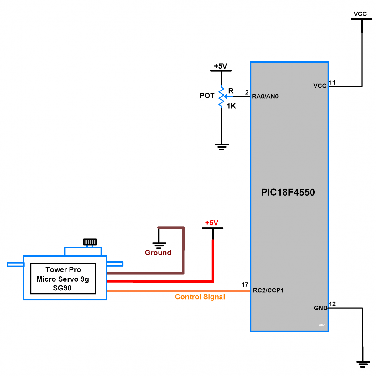
Change the Angle of Servo Motor with Potentiometer using PIC18F4550
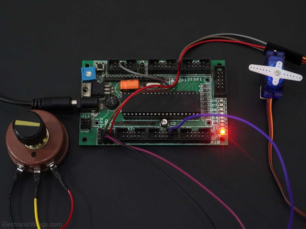
Now let’s program PIC18F4550 to generate 50Hz PWM to control Servo Motor in an angle between -90° to +90° rotation using external potentiometer knob.
- Here we are using ADC channel 0 of PIC18F4550 to read external potentiometer knob and according to the ADC value, we are varying duty cycle of PWM.
- Refer ADC in PIC18F4550 for more information on ADC in PIC18F4550.
Connection Diagram of Servo Motor and Pot to PIC18F4550
Code for Servo control using POT with PIC18F4550
/*
 * Servo control using POT with PIC
 * http://www.electronicwings.com
 */

#include <pic18f4550.h>
#include <stdio.h>
#include <math.h>
#include "Configuration_header_file.h"
#include "ADC_Header_File.h"

#define MINTHR              8000
#define RESOLUTION          488

#define InternalOsc_8MHz    8000000
#define InternalOsc_4MHz    4000000
#define InternalOsc_2MHz    2000000
#define InternalOsc_1MHz    1000000
#define InternalOsc_500KHz  500000
#define InternalOsc_250KHz  250000
#define InternalOsc_125KHz  125000
#define InternalOsc_31KHz   31000

#define Timer2Prescale_1    1
#define Timer2Prescale_4    4
#define Timer2Prescale_16   16

void PWM_Init()             /* Initialize PWM */
{
    TRISCbits.TRISC2 = 0;   /* Set CCP1 pin as output for PWM out */
    CCP1CON = 0x0C;         /* Set PWM mode */
}

int setPeriodTo(unsigned long FPWM)/* Set period */
{
    int clockSelectBits, TimerPrescaleBits;
    int TimerPrescaleValue;
    float period;
    unsigned long FOSC, _resolution = RESOLUTION;

    if (FPWM < MINTHR)    {TimerPrescaleBits = 2; TimerPrescaleValue = Timer2Prescale_16;}
    else                  {TimerPrescaleBits = 0; TimerPrescaleValue = Timer2Prescale_1;}

    if (FPWM > _resolution)               {clockSelectBits = 7; FOSC = InternalOsc_8MHz;}
    else if (FPWM > (_resolution >>= 1))  {clockSelectBits = 6; FOSC = InternalOsc_4MHz;}
    else if (FPWM > (_resolution >>= 1))  {clockSelectBits = 5; FOSC = InternalOsc_2MHz;}
    else if (FPWM > (_resolution >>= 1))  {clockSelectBits = 4; FOSC = InternalOsc_1MHz;}
    else if (FPWM > (_resolution >>= 1))  {clockSelectBits = 3; FOSC = InternalOsc_500KHz;}
    else if (FPWM > (_resolution >>= 1))  {clockSelectBits = 2; FOSC = InternalOsc_250KHz;}
    else if (FPWM > (_resolution >>= 1))  {clockSelectBits = 1; FOSC = InternalOsc_125KHz;}
    else                                  {clockSelectBits = 0; FOSC = InternalOsc_31KHz;}

    period = ((float)FOSC / (4.0 * (float)TimerPrescaleValue * (float)FPWM)) - 1.0;
    period = round(period);

    OSCCON = ((clockSelectBits & 0x07) << 4) | 0x02;
    PR2 = (int)period;
    T2CON = TimerPrescaleBits;
    TMR2 = 0;
    T2CONbits.TMR2ON = 1;  /* Turn ON Timer2 */
    return (int)period;
}

void SetDutyCycleTo(float Duty_cycle, int Period)/* Set Duty cycle for given period */
{
    int PWM10BitValue;

    PWM10BitValue = 4.0 * ((float)Period + 1.0) * (Duty_cycle/100.0);
    CCPR1L = (PWM10BitValue >> 2);
    CCP1CON = ((PWM10BitValue & 0x03) << 4) | 0x0C;
}

int main()
{
    float Duty_Scale;
    int Period;
    ADC_Init();
    PWM_Init();                 /* Initialize PWM */
    Period = setPeriodTo(50);   /* 50Hz PWM frequency */
    /* Note that period step size will gradually increase with PWM frequency */
    while(1)
    {
        /* Scale Duty Cycle in between 3.0-12.0 */
        Duty_Scale = (((float)(ADC_Read(0)/4.0)*9.0)/255.0) + 3.0;
        SetDutyCycleTo(Duty_Scale, Period);
    }
}
Video of Controlling Servo Motor using Potentiometer with PIC18F4550
Components Used
Powered by

Downloads
Comments12
Join the discussion — share a question or tip.
- LE
Can this chip (PIC18F4550) control many servo motors (12 items) simultaneously?
- PR
if my oscillator frequency is constant to 8MHZ then can i use timer2 postscallar to obtain 50HZ as output frequency
- PR
Duty_Scale = (((float)(ADC_Read(0)/4.0)*9.0)/255.0) + 3.0; please explin me this calculation
- BL
and Why MINTHR and resolution are 8000 and 488?
- BL
Replying to @lokeshc
Now i know overview but specifically why 8000 and 488 values are used?
- MA
Replying to @blarblublublar
i could have a possible explanation for these values (of course i could be wrong....but still)...........typical operating frequency (Fosc) of pic is 8 MHz......now minimum and maximum prescale values of timer2 are 1 and 16 respectively........and the formula to find out value of PR2 register is PR2 = (Fosc/(4*Fpwm*TMR2_prescale_value))-1 as per datasheet.......since PR2 is an 8 bit register, the min and maximum values it can take for generating a valid pwm frequency is 1 and 255 respectively.......so to find out MINTHR value we substitute in above formula PR2 = 255 & TMR2_prescale_value = 1, and we get Fpwm = 7812.5 Hz which can be rounded off to 8000 Hz approx., and thus MINTHR = 8000..............and then to find out RESOLUTION value we substitute in above formula PR2 = 255 & TMR2_prescale_value = 16, and we get Fpwm = 488.28125 Hz which can be rounded off to 488 approx., and thus RESOLUTION = 488.............i guess this is the reason for choosing 8000 and 488..........if somebody as a different explanation then we all would be glad to know.
- BL
what is MINTHR?
- NG
Hi, i don't understand define MINTHR why is 8000 and next line of code why is 488. thanks