Getting started with PIC18F4550 and MPLABX IDE
Start developing code for PIC18F4550 using MPLABX IDE.
Introduction
There are various development environments available for the PIC18f4550 controller.
We can use the following IDEs for development:
- MPLABX IDE
- MikroC
C Compilers for PIC 18f4550
- XC8
- Hi-Tech
- C18
After code development, for loading flash memory we can use this kit
- PIC kit1
- PIC kit2
- PIC kit3
- ICD
Here we are going to develop a simple LED blinking project using MPLABX IDE with XC8 compiler and flash the PIC18f4550 chip using PIC kit2.
MPLABX IDE is an Integrated Development Environment that is developed by Microchip.
It is used to develop a code for PIC microcontrollers.
Let’s start with MPLABX IDE.
1. Download compiler XC8 and Install it.
2. Download MPLABX IDE and install it also.
3. There are many hardware Programmer available for PIC like PicKit2, PicKit3, USBPicProg.
- Here PickKit2 is used to download the program into the device.
4. Now Open MPLABX IDE.
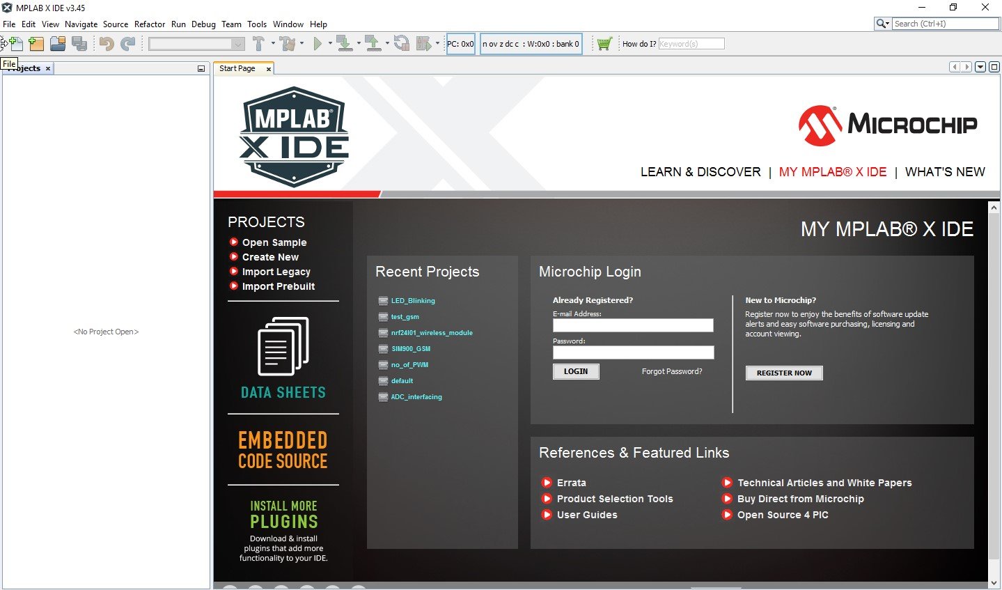
5. Now Create a new project for LED blinking.
- Select File -> New Project
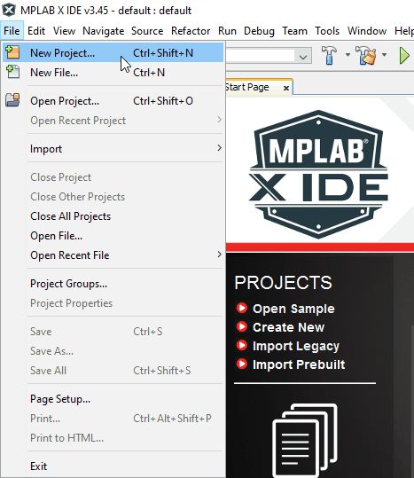
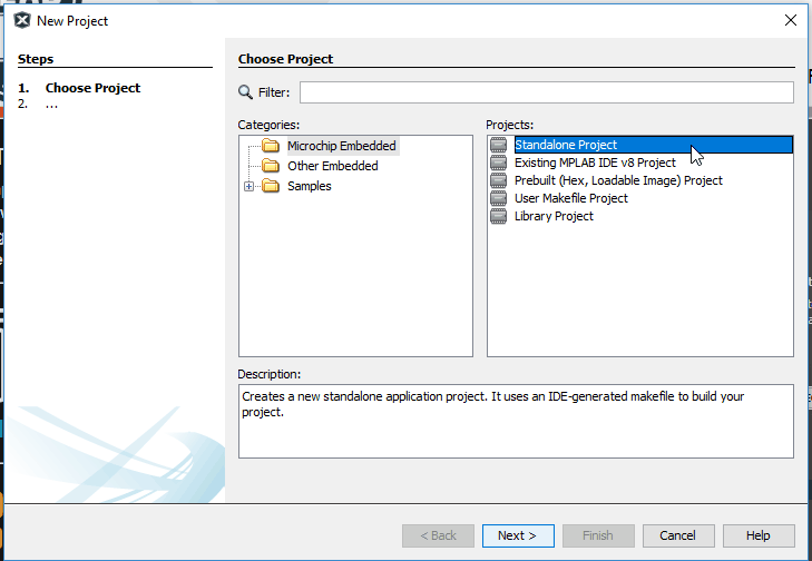
6. After selecting new project following window will pop-up.
- Select Microchip Embedded -> Select Standalone and click to next.
7. Select Device and their Family
- Here PIC18 family is used and PIC18F4550 device. After selecting click on next.
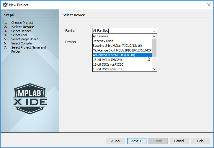
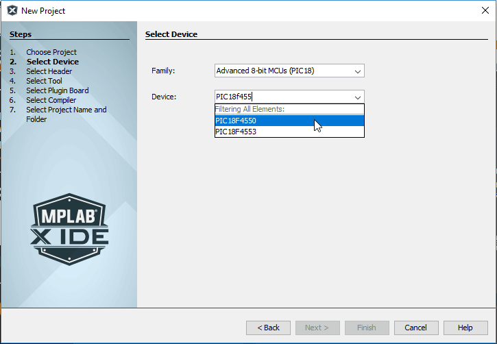
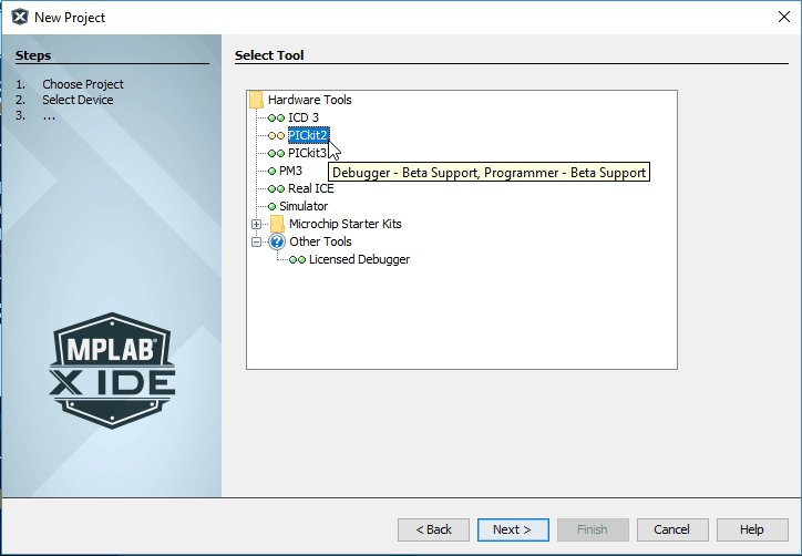
8. Window for selecting tool will Pop-up after clicking on next
- Here PicKit2 Program downloading tool is used. Then click on Next.
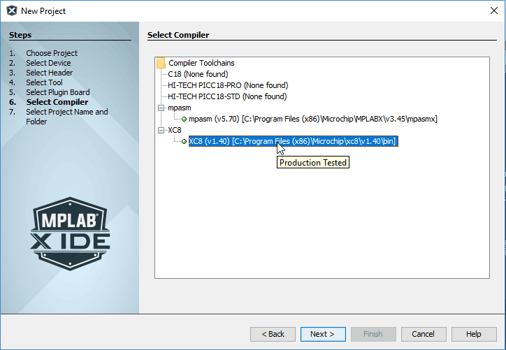
9. Now select Compiler. Here XC8 is used and click Next.
10. Name a Project e.g. LED_Blinking_demo also set Path for Project Folder and Click on Finish.

Now our project is displayed in Project window.
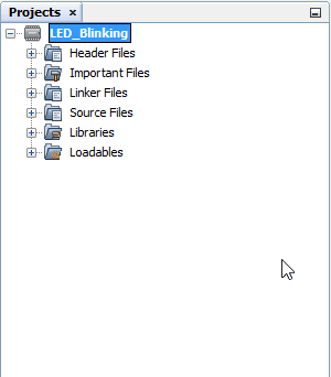
- The source file contains Main Code and other supporting files for a header (optional).
- Now in PIC18f4550, we need to configure some registers or bits like WDT, MCLRE’, FOSC, etc.
- We can write these configurations in our C code as follows:
#pragma config FOSC = INTOSC_EC
#pragma config WDT = OFF
#pragma config MCLRE = OFF
- But PIC18F4550 has more configuration Registers so they are set to default and the compiler generates warnings for these registers. So to configure these registers MPLABX provides one simple way which is as follows:
11. Go to Window -> PIC Memory Views -> Select Configuration Bits
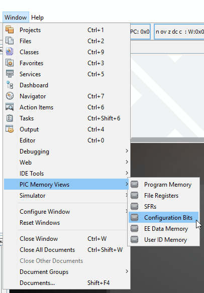
Then window Popup as follows:
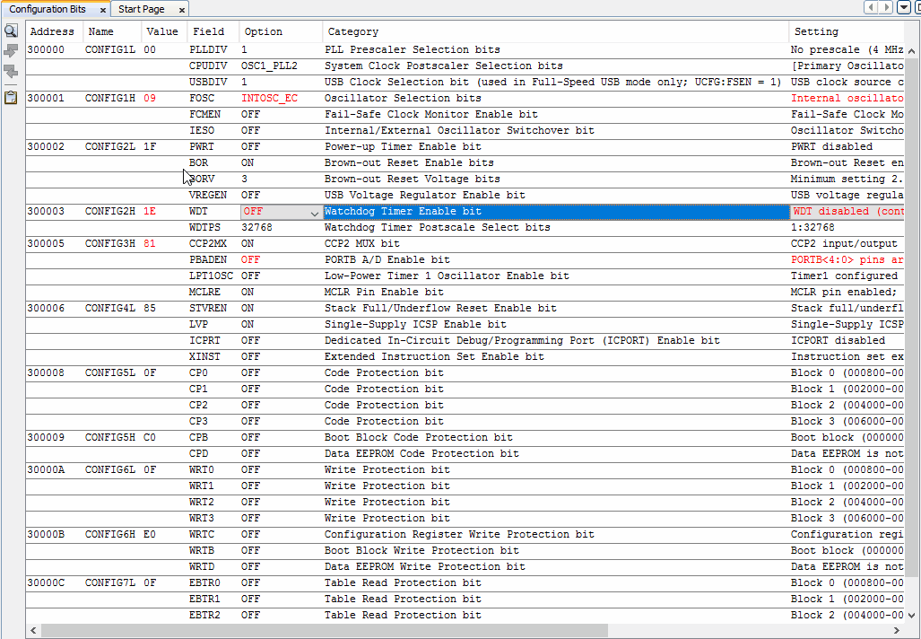
- Configure these bits according to requirement and click on the button “Generate Source Code to Output” given on the bottom side.
- Copy the Generated Source Code and paste it in a header file.
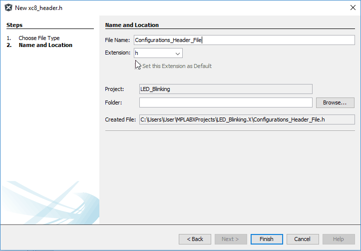
12. To do this 1st Create a Header file
- Right Click on Header in project -> Select new -> Select C Header File
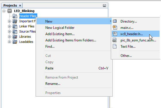
- Name Header File and click on Finish
- Now we have to write the main code for LED blinking.
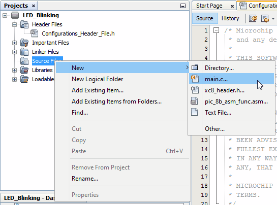
13. Create the Main file for developing code.
- Right Click on Source in the project -> Select new -> Select C Main File
- To write code in Assembly, select the ASM file.
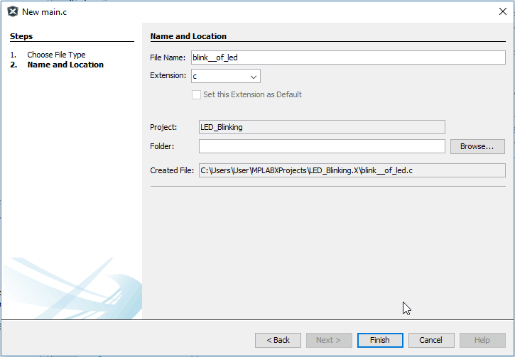
- Give name to C file and click on finish.
14. Now write a simple application Code.
- Simple C Program for LED blinking.
PIC18F4550 LED Blinking Program
/*
 Led blinking using PIC18F4550
 http://www.electronicwings.com
 */

#include "Configurations_Header_File.h"  /*Header file for Configuration Bits*/
#include <pic18f4550.h>                  /*Header file PIC18f4550 definitions*/

void MSdelay(unsigned int);

void main()
{
    OSCCON=0x72;                /* Use internal oscillator of 8MHz Frequency */
    TRISB=0x00;                 /* Set direction of PORTB as OUTPUT to which LED is connected */
    while(1)
    {
        LATB = 0xFF;            /* Turn ON LED for 500 ms */
        MSdelay (500);
        LATB = 0x00;            /* Turn OFF LED for 500 ms */
        MSdelay (500);
    }
}
void MSdelay(unsigned int val)
{
 unsigned int i,j;
 for(i=0;i<val;i++)
     for(j=0;j<165;j++);         /*This count Provide delay of 1 ms for 8MHz Frequency */
 }
15. Now Build Project.
- There is one Hammer like shape, click on it to build a project.

- After building a Project, output Window appears which gives errors and warnings if any otherwise gives message Build Successful.
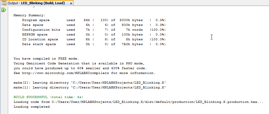
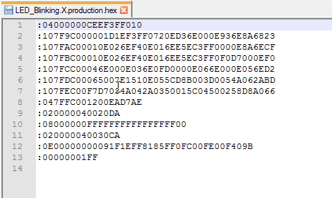
- Following is generated Hex File which needs to load in PIC device.
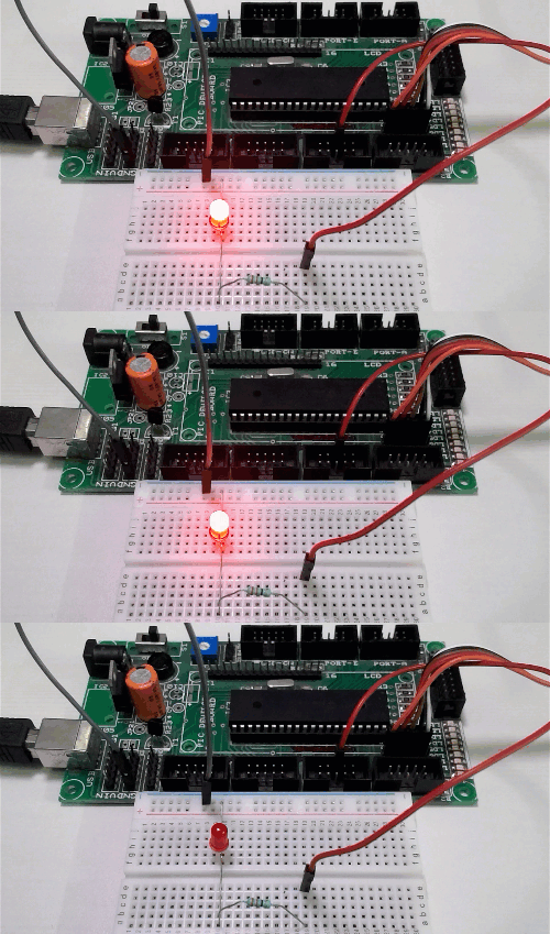
After uploading the above program connect LED to the PIC microcontroller, it will start blinking as shown below.
LED Blinking Output
Components Used
Powered by

Downloads
Comments19
Join the discussion — share a question or tip.
- DN
Hello, Could anyone please share which Proteus version used for the Proteus simulation? Object is to simulate the same project by using the provided project.
- MA
Hi This is very useful to me....can you please explain me what is happening in the for loop. Clear with the function. Give me an explanation for the for loop.
- HA
Hi, Anyone kindly suggests the programmer kit for PIC18LF45K50 MCU.
- SA
Can help me for c program sorting array ascending n descending order with alogrithm
- AU
There are many online sorting algorithm you can find across. Anyway what perticular help you required there ?
- YA
I will like to know what development board are you using? I am looking forward to learn and develop on PIC.
- BA
Please I'm new in programming. Why the use of 0xFF to set the output of the MCU to 1 'cause I know that's an hexadecimal. Also the use of OSCCON = 0X72 to set the frequency?
- LO
For setting GPIO pin to High we have to send 1 to those pin. Here, complete GPIO port (8 GPIO pins) pin set to High by sending 0xff (1111 1111) to them. You can send 0x01 for 1 led only. Yes, OSCCON is used to set which frequency is used i.e. Internal, external or timer. You can find detail about this register in datasheet.
- BA
Replying to @lokeshc
Thanks so much lokeshc. This site is really helpful for beginners like myself. Thanks once again
- BA
Replying to @lokeshc
I tried implementing it on breadboard using PICKIT3 but It's showing "Target device was not found (could not detect target voltage VDD). you must connect to a target device to use PICkit3". I don't understand what it's saying. And it's not working. What can I do? Please help me out
- AK
void MSdelay(unsigned int val) { unsigned int i,j; for(i=0;i<val;i++) for(j=0;j<165;j++); /*This count Provide delay of 1 ms for 8MHz Frequency */ } sir , what is the calculation behind to get 1 ms from 16MHz Frequency , hw do i set the value for 'J' whwn MSdelay(500) will be called?? pl....
- AK
as OSCCON=0X72; So, it shuld be 16MHZ, how it coming to 8MHZ as defined in programme. HFINTOSC is at 111 as below mention in datashhet.. IRCF<2:0>: Internal RC Oscillator Frequency Select bits(2) 111 = HFINTOSC – (16 MHz) 110 = HFINTOSC/2 – (8 MHz) 101 = HFINTOSC/4 – (4 MHz) 100 = HFINTOSC/8 – (2 MHz) 011 = HFINTOSC/16 – (1 MHz)(3) Could u explain sir???? tnx
- AK
Pl ignore earlier comment . that was correct at 8mhz, i considered mcu 18f46k22 as that was for 4550 mcu. IRCF2:IRCF0: Internal Oscillator Frequency Select bits 111 = 8 MHz (INTOSC drives clock directly) 110 = 4 MHz 101 = 2 MHz 100 = 1 MHz(3) 011 = 500 kHz 010 = 250 kHz 001 = 125 kHz 000 = 31 kHz (from either INTOSC/256 or INTRC directly)(2)
- PM
Can help me i am very new for C program
- PM
Hi sir I looking for inter lock with key pad and control from Bluetooth with lcd display with 4 diget pass word
- RA
Great info, but I'll hope you can also add code from CCS. And a USB section :)