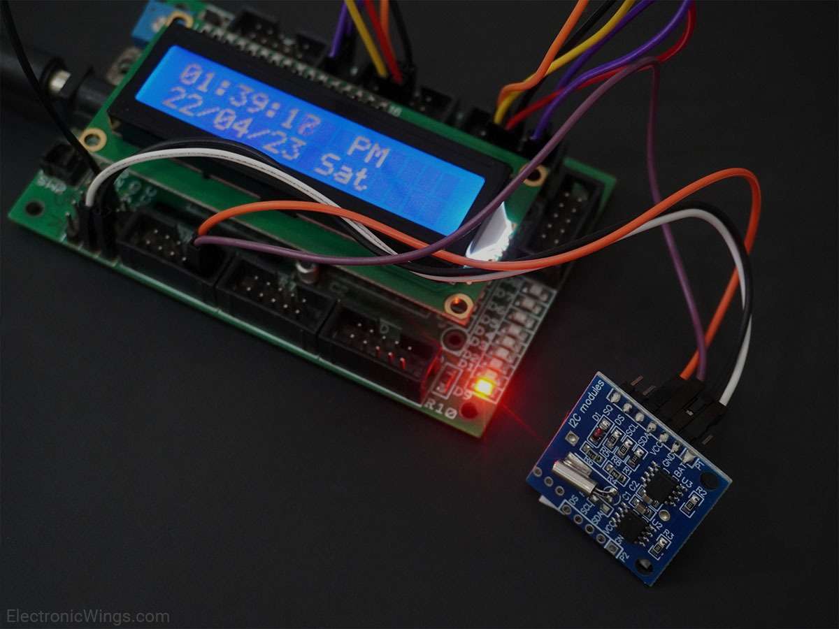
Real Time Clock RTC DS1307 interfacing with PIC18F4550
DS1307 is a two-wire (I2C) serial interface RTC (Real Time Clock) with 56 bytes of nonvolatile RAM. This provides clock and calendar with a second, minute, hour, day, date, month, and year.
Introduction
Real-Time Clock (RTC) is used for tracking time and maintaining a calendar.
Many applications require keeping a record of time/date when certain events occur. RTCs are useful in such applications.
RTCs come in handy in data logging applications. They are also used in devices like computers, laptops, and mobile phones.
RTCs are powered by external batteries so that they can maintain time and data even in the case of power failures.
RTCs have several registers that keep a track of time and date.
In order to use an RTC, we need to first program it with the current date and time. Once this is done, the RTC registers can be read at any time to know the time and date.
DS1307 is an RTC that works on I2C protocol.
For information on PIC18F4550 I2C protocol, refer the topic PIC18F4550 I2C in PIC Inside section
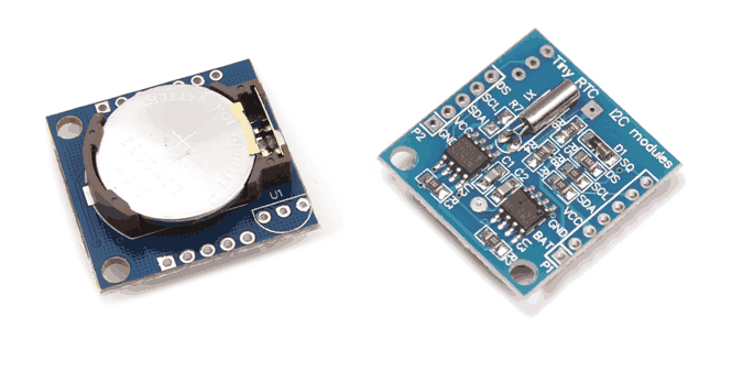
For information on DS1307 and how to use it, refer to the topic Real-Time Clock RTC DS1307 Module in the sensors and modules section.
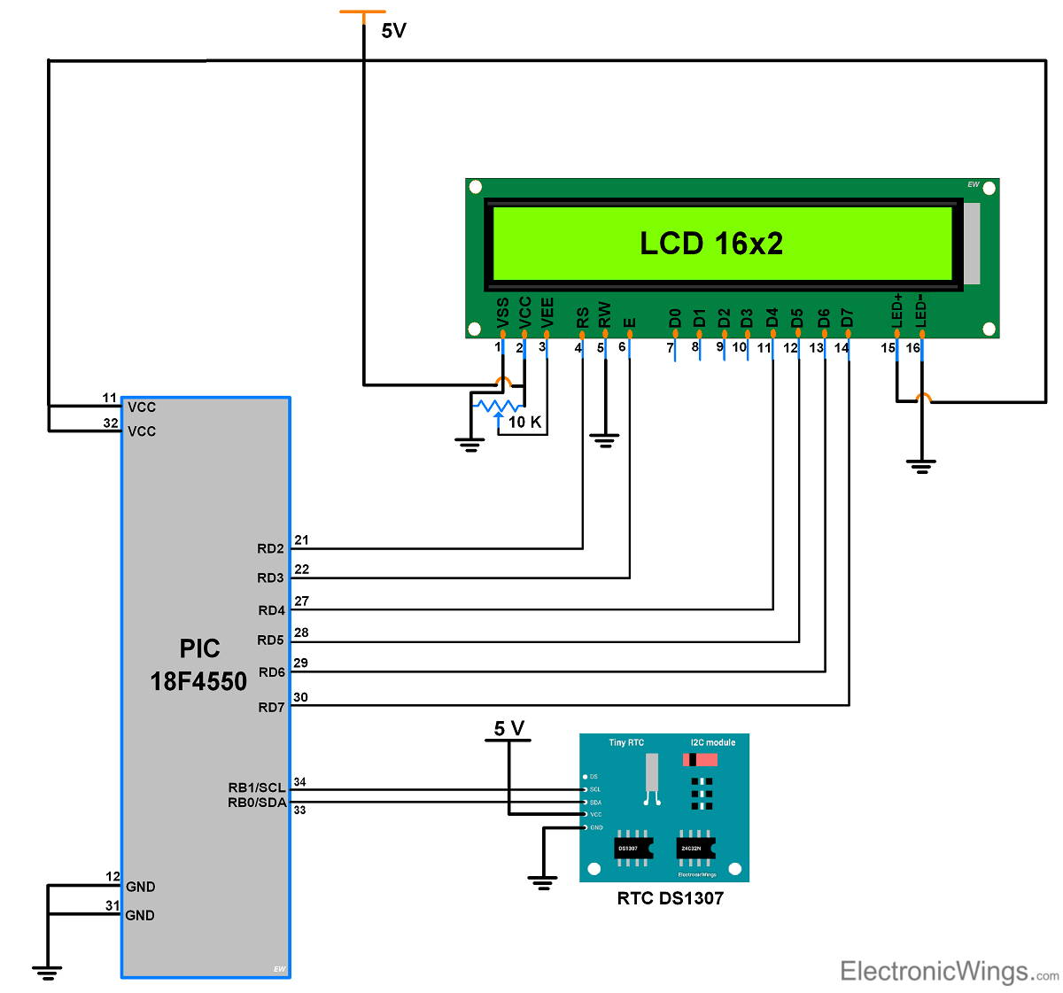
Connection Diagram of RTC DS1307 With PIC18F4550
Programming steps for RTC DS1307
Initially, while using RTC first time, we have to set the clock and calendar values, then RTC always keeps updating this clock and calendar values.
We will set the RTC clock and calendar values in 1st step and in 2nd step, we will read these values.
Step1: Setting Clock and Calendar to RTC DS1307
- In RTC coding, we require the first RTC device address (slave address) through which the microcontroller wants to communicate with the DS1307.
- DS1307 RTC device address is 0xD0 (given in datasheet).
- Initialize I2C in PIC18F4550.
- Start I2C communication with device writes address i.e. 0xD0.
- Then, Send the Register address of Seconds which is 0x00, then send the value of seconds to write in RTC. RTC address gets auto-incremented so next, we only have to send the values of minutes, hours, day, date, month, and year.
- And stop the I2C communication.
void RTC_Clock_Write(char sec, char min, char hour, char AM_PM)					/* function for clock */
{
    hour = (hour | AM_PM);     /* whether it is AM or PM */
	I2C_Start(device_id_write);/* start I2C comm. with device slave address*/
	I2C_Write(0);			   /* write 0 location for sec value */
	I2C_Write(sec);			   /* write second value on 00 location */
	I2C_Write(min);			   /* write min value on 01 location */
	I2C_Write(hour);		   /* write hour value on 02 location */
	I2C_Stop();				   /* stop I2C communication */
}

void RTC_Calendar_Write(char day, char date, char month, char year)	/* function for calendar */
{
	I2C_Start(device_id_write);/* start I2C comm. with device slave address */
	I2C_Write(3);			   /* write on 3 location for day value */
	I2C_Write(day);			   /* write day value on 03 location */
	I2C_Write(date);		   /* write date value on 04 location */
	I2C_Write(month);		   /* write month value on 05 location */
	I2C_Write(year);		   /* write year value on 06 location */
	I2C_Stop();
}
Step2: Reading Time and Date value from RTC DS1307
- In the second step, we will read the data from the RTC, i.e. second, minute, hours, etc.
- Start the I2C communication with device writes address i.e. 0xD0.
- Then write the register value from where we have to read the data (we read from location 00 i.e. read the second).
- Then send repeated start with device read address i.e. 0xD1.
- Now Read the data with acknowledgment from location 00.
- For reading the last location always read with the negative acknowledgment, then the device will understand this is the last data to read from the device.
- For read next Byte, the location of the register address will get auto-incremented.
Program for Reading Date and Time using PIC18F4550
/*
 * PIC18F4550 interfacing with RTC DS1307
 * http://www.electronicwings.com
 */


#include <stdio.h>
#include "Configuration_Header_File.h"
#include "16x2_LCD_4bit_File.h"
#include <pic18f4550.h>
#include "I2C_Master_File.h"

#define device_id_write 0xD0
#define device_id_read 0xD1

int sec,min,hour;
int Day,Date,Month,Year;

void RTC_Read_Clock(char read_clock_address)
{
    I2C_Start(device_id_write);
    I2C_Write(read_clock_address);     /* address from where time needs to be read*/
    I2C_Repeated_Start(device_id_read);
    sec = I2C_Read(0);                 /*read data and send ack for continuous reading*/
    min = I2C_Read(0);                 /*read data and send ack for continuous reading*/
    hour= I2C_Read(1);                 /*read data and send nack for indicating stop reading*/

}

void RTC_Read_Calendar(char read_calendar_address)
{
    I2C_Start(device_id_write);
    I2C_Write(read_calendar_address); /* address from where time needs to be read*/
    I2C_Repeated_Start(device_id_read);
    Day = I2C_Read(0);                /*read data and send ack for continuous reading*/
    Date = I2C_Read(0);               /*read data and send ack for continuous reading*/
    Month = I2C_Read(0);              /*read data and send ack for continuous reading*/
    Year = I2C_Read(1);               /*read data and send nack for indicating stop reading*/
    I2C_Stop();
}

void main()
{

    char secs[10],mins[10],hours[10];
    char date[10],month[10],year[10];
    char Clock_type = 0x06;
    char AM_PM = 0x05;
    char days[7] = {'S','M','T','W','t','F','s'};
    OSCCON=0x72;                    /*Use internal oscillator and
                                     *set frequency to 8 MHz*/
    I2C_Init();                     /*initialize I2C protocol*/
    LCD_Init();                     /*initialize LCD16x2*/
    LCD_Clear();
    MSdelay(10);
    while(1)
    {
        RTC_Read_Clock(0);              /*gives second,minute and hour*/
        I2C_Stop();
        if(hour & (1<<Clock_type)){     /* check clock is 12hr or 24hr */

            if(hour & (1<<AM_PM)){      /* check AM or PM */
                LCD_String_xy(1,14,"PM");
            }
            else{
                LCD_String_xy(1,14,"AM");
            }

            hour = hour & (0x1f);
            sprintf(secs,"%x ",sec);   /*%x for reading BCD format from RTC DS1307*/
            sprintf(mins,"%x:",min);
            sprintf(hours,"Tim:%x:",hour);
            LCD_String_xy(0,0,hours);
            LCD_String(mins);
            LCD_String(secs);
        }
        else{

            hour = hour & (0x3f);
            sprintf(secs,"%x ",sec);   /*%x for reading BCD format from RTC DS1307*/
            sprintf(mins,"%x:",min);
            sprintf(hours,"Tim:%x:",hour);
            LCD_String_xy(0,0,hours);
            LCD_String(mins);
            LCD_String(secs);
        }

        RTC_Read_Calendar(3);        /*gives day, date, month, year*/
        I2C_Stop();
        sprintf(date,"Cal %x-",Date);
        sprintf(month,"%x-",Month);
        sprintf(year,"%x ",Year);
        LCD_String_xy(2,0,date);
        LCD_String(month);
        LCD_String(year);

    /* find day */
        switch(days[Day])
        {
            case 'S':
                        LCD_String("Sun");
                        break;
            case 'M':
                        LCD_String("Mon");
                        break;
            case 'T':
                        LCD_String("Tue");
                        break;
            case 'W':
                        LCD_String("Wed");
                        break;
            case 't':
                        LCD_String("Thu");
                        break;
            case 'F':
                        LCD_String("Fri");
                        break;
            case 's':
                        LCD_String("Sat");
                        break;
            default:
                        break;

        }

    }
}
Components Used
Powered by

Downloads
Comments10
Join the discussion — share a question or tip.
- JO
Hi everyone. I've a problem. I 'm using pic18f4520 and ds1307. i'm managing to set up the inicial time for all componentes (seconds, hours, day,etc) except for the minutes, on the addr 0x01. it begins always on 00 minutes. Anyone has an ideia of what could be wrong? Thanks
- LA
while simulating on proteus it shows me following error : [PIC18] PC=0x0856. The SCSx bits have been set. This feature is not modelled - the model continues to clock itself as before. [U1] please help
- LA
Please share library for RTC ds1307 module in proteus
- AB
LCD display showing only tim:0: 0: 0 Cal:0-0-0 Sun
- OL
Hi, The RTC DS1307 is very unstable and inaccurate. We are talking about 2-3 minutes pr. month drifting off. Buy a DS3231 chip on a breakout board from Ebay instead.
- CA
Buenas tardes, No me funcionó, ademas de eso puedo cambiar los pines de SDA, SCL? a los pines RC0 y RC1
- KH
did this works with pic 18F47K40??