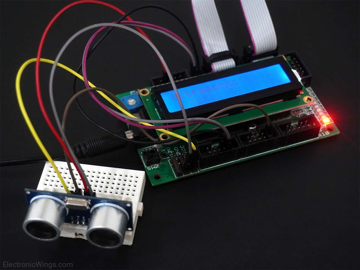
Ultrasonic Module HC-SR04 interfacing with PIC18F4550
The ultrasonic module HC-SR04 is generally used for finding distance value and obstacle detection. It can operate in the range of 2-400cm.
Ultrasonic Sensor HC-SR04
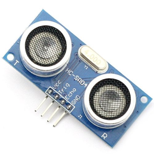
Ultrasonic Module HC-SR04 works on the principle of SONAR and RADAR system.
- The HC-SR04 module has an ultrasonic transmitter, receiver, and control circuit on a single board.
- The module has only 4 pins, Vcc, Gnd, Trig, and Echo.
- When a pulse of 10µsec or more is given to the Trig pin, 8 pulses of 40 kHz are generated. After this, the Echo pin is made high by the control circuit in the module.
- The echo pin remains high till it gets an echo signal of the transmitted pulses back.
- The time for which the echo pin remains high, i.e. the width of the Echo pin gives the time taken for generated ultrasonic sound to travel towards the object and return.
- Using this time and the speed of sound in air, we can find the distance of the object using a simple formula for distance using speed and time.
For more information about ultrasonic module HC-SR04 and how to use it, refer to the topic Ultrasonic Module HC-SR04 in the sensors and modules section.
Connection Diagram of Ultrasonic Sensor to PIC18F4550
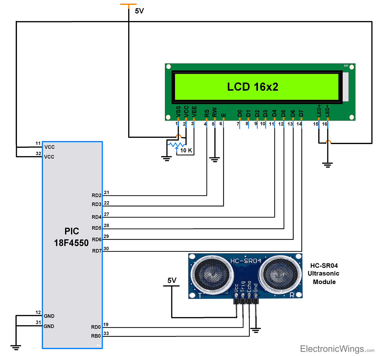
Measure the Distance using HC-SR04 and PIC18F4550
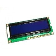
Here let’s design an application in which we will find a distance to an object by interfacing ultrasonic module HC-SR04 with PIC18F4550 and display the distance on a 16x2 LCD.
Steps of Programming
- PIC18F4550 microcontroller needs to transmit at least 10 us trigger pulse to the HC-SR04 Trig Pin.
- After getting a trigger pulse, HC-SR04 automatically sends eight 40 kHz sound waves and waits for rising edge output at the Echo pin.
- When the rising edge capture occurs at the Echo pin which is connected to the input of PIC18F4550, start Timer of PIC18F4550 and again wait for the falling edge on the Echo pin.
- As soon as the falling edge is captured at the Echo pin, the microcontroller reads the count of the Timer. This time count is used to calculate the distance to an object.
Calculation (distance in cm)
Sound velocity = 343 m/s = 34300 cm/s
= (34300 * TIMER) / 2
= 17150 * (TIMER)
Now, if we selected 8 MHz oscillator frequency for PIC18F4550, timer frequency in PIC18F4550 will be 2 MHz. So time to execute 1 instruction is 0.5 us.
So timer gets incremented after 0.5 us time elapse.
= 17150 * (TIMER value) x 0.5 x 10^-6 cm
= 0.5 * (TIMER value)/58.30 cm
=0.5 * (TIMER value) / 58.30 cm
or
= (TIMER value) / 117 cm
Ultrasonic Sensor HC-SR04 Code for PIC18F4550
/*
  Interfacing Ultrasonic module HC-SR04 with PIC18F4550
  for finding distance to an object

  http://www.electronicwings.com
 */


#include <xc.h>
#include <pic18f4550.h>
#include <stdio.h>
#include "Configuration_Header_File.h"
#include "16x2_LCD_4bit_File.h"

void Trigger_Pulse_10us();

#define _XTAL_FREQ 8000000	/* Define freq */
#define Trigger_Pulse LATD0	/* Define Trig pin of HC-SR04 */

void main()
{
    float Distance;
    int Time;
    float Total_distance[10];
    OSCCON=0x72;		/* Use internal oscillator frequency */
    TRISB = 0xff;		/* Make PORTB as Input port*/
    TRISD = 0;			/* Make PORTD as Output port*/
    INTCON2bits.RBPU=0;		/* Enable PORTB Pull-ups */
    LCD_Init();
    Trigger_Pulse = 0;
/* Enable 16-bit TMR1 Register,No prescale, internal clock, Timer OFF */
    T1CON = 0x80;
    TMR1IF = 0;			/* Make Timer1 Overflow Flag to '0' */
    TMR1=0;			/* Load Timer1 with 0 */
    LCD_String_xy(1,1," Distance:");
while(1)
	{
    	Trigger_Pulse_10us();	/* Transmit 10us pulse to HC-SR04 */
    	while(PORTBbits.RB0==0);	/* Wait for rising edge at Echo pin */
    	TMR1=0;			/* Load Timer1 register with 0 */
    	TMR1ON=1;			/* Turn ON Timer1*/
    	while(PORTBbits.RB0==1 && !TMR1IF);/* Wait for falling edge */
    	Time = TMR1;		/* Copy Time when echo is received */
    	TMR1ON=0;			/* Turn OFF Timer1 */
    	Distance = ((float)Time/117.00);/* Distance =(velocity x Time)/2 */
    	sprintf(Total_distance,"%.03f",Distance);
    	LCD_String_xy(2,1,Total_distance);
    	LCD_String("  cm");
    	MSdelay(50);
	}
}

void Trigger_Pulse_10us()
{
    Trigger_Pulse = 1;
    __delay_us(10);
    Trigger_Pulse = 0;
}
Video of Distance Measurement using Ultrasonic HC-SR04 Sensor
Components Used
Powered by
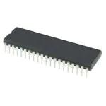
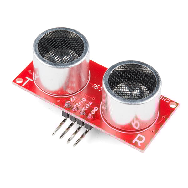
Ultrasonic module HC-SR04 is generally used for finding distance value and obstacle detection. It can operate in the range 2cm-400cm.
474-SEN-15569
Downloads
Comments43
Join the discussion — share a question or tip.
- MO
i was unable to convert the code into assembly code??
- GA
Hello guys, I have a problem. I'm using dsPIC33FJ64MC802 with pikit3 and C30 compiler and I can't config the ultrasonic sensor, HC-SR04. Also, I am using 4x20 LCD. Can someone help me with this problem? This is my code. void initPLL(void) { // Configure PLL prescaler, PLL postscaler, PLL divisor PLLFBD = 41; // M = 43 FRC //PLLFBD = 30; // M = 32 XT CLKDIVbits.PLLPOST=0; // N1 = 2 CLKDIVbits.PLLPRE=0; // N2 = 2 // Initiate Clock Switch to Internal FRC with PLL (NOSC = 0b001) __builtin_write_OSCCONH(0x01); // FRC //__builtin_write_OSCCONH(0x03); // XT __builtin_write_OSCCONL(0x01); // Wait for Clock switch to occur while (OSCCONbits.COSC != 0b001); // FRC //while (OSCCONbits.COSC != 0b011); // XT // Wait for PLL to lock while(OSCCONbits.LOCK!=1) {}; } void prvSetupHardware( void ) { ADPCFG = 0xFFFF; initPLL(); LCD_init(); } /*-----------------------------------------------------------*/ int main( void ) { prvSetupHardware(); float Distance; int Time; float Total_distance[10]; _TRISB6=1; _RB6=0; _TRISB7=0; _RB7=0; T1CON = 0x80; TMR1 = 0; LCD_Goto(1,1); LCD_printf("Distance:"); while (1) { _RB7 = 1; __delay_us(10); _RB7 = 0; while(!_RB6); TMR1=0; T1CONbits.TON = 1; while(_RB6); Time = TMR1; T1CONbits.TON = 0; Distance = ((float)Time/118.00); sprintf(Total_distance,"%.03f",Distance); LCD_Goto(2,1); LCD_printf(Total_distance); __delay_us(10); } }
- SZ
I want to convert the distance measured to percentage. All works well until I'm changing "cm" to "%" inside LCD_String(" cm"); the LCD shows the only a constant number and the number doesn't change. Can u please explain : void LCD_String(const char *msg) { while((*msg)!=0) { LCD_Char(*msg); msg++; } }
- BL
while(PORTBbits.RB0==1 && !TMR1IF);/* Wait for falling edge */ if we get falling edge, but do we still need to wait Timer overflow?
- LE
hey blarblublublar, the code isnt waiting for an overflow...the reason why the program checked the TIMER1 interrupt flag was because when the timer overflows and set the flag, TMR1 register overflows to 0000h(in other words it restarts the count from zero) and if you read the value of the TMR1 register it wouldn't give the desired results...so for example, it more or less prevents the sensor from reading that the distance is 500cm and then the code says its 2cm...hope i helped :)
- JA
I'm using MPLAB IDE v8. 89 .It is giving an error of unable to locate xc.h Configuration_Header_file.h and 16x2_LCD_4bit_File.h I have also downloaded the project file and it is in zip format. Where should I extract the above files to remove the error
- RO
Hi ! I'm doing a Embebids Project with the Pic 18F4580 .. Does this configurations work in the pic ? I'm doing the alterations oh the regists of ports, etc .. I'm doing a Ultrasonic that turn on some leds and activats a buzzer when it's too close of the ultrasonic, and with the LCD 16x2 i'm showing the distance and the temperature, i did my sorce files and header files, only some warnings, no errors , in my main i called the functions but the project dosen't work. I don't know if you can help me ?
- LE
bro you got to send the code for us to look at.... no code == no help
- BL
LCD_String_xy(1,1," Distance:"); Distance argument mean incompatible pointer types. Because Distance is float and LCD_String_xy(char, char, const char *)
- BL
Distance of Object(cm)= 17150 * (TIMER value) x 0.5 x 10^-6 cm Distance of Object(cm)= 0.5 * (TIMER value)/58.30 cm How this value get? how do u calculate it?
- SYsyarifmuhd24· edited
hello why my codding is wrong?? and its wrong at #include pic18f4550.h and #include xc.h in my .c file and .h file??
- JO
Can i ask u something..when i try to build this source code it say that cant open "Configuration_Header_File.h no such file and directory..can u help me solve this
- AU
there is veriable defined in above program => int Time; ( which is from -32768 to +32768 i.e. it has 32768 limit in positive value beyond that it will start negative count ) which is int so that above program will measure distance correctly upto limit you mentioned. if you want more limit then simply use unsigned int => unsigned int Time; ( which can count from 0 to 65535 ) so i think you should try replacing int with unsigned int type of Time variable.
- DU
Hello, How can I convert the above code to be compatible with microcontroller tm4c123gh6ph?
- AU
are you using energia or code composer to program ? whatever you use you need to go through all steps as mentioned in above code like ********************************************************* first you have to define two digital pins on it one as input and one as output connect output pin to trigger pin and input pin to echo pin of hcsr04 . pass 10us pulse on output pin and wait for rising edge at echo pin. as rising edge arrive start timer/counter to count time until the falling edge detect at echo pin on falling edge detect stop timer/counter. finally convert that measured count to distance with formula. ***********************************************************
- MI
Hello I am getting an error where t display 0.120cm and does not continue to read distance, HELP
- IS
I have noticed that this works ok when using a a perpendicular object to bounce the signal off. But it fails if you put this object at 45 degrees to the sensor and reports a 0.034 result on the lcd which it cannot recover from. It continues with this error in the while loop. Any ideas on the correction to this problem? I can understand that the signal is being reflected and no return signal can be seen by echo but when you return the object to perpendicular it should recover - but it doesn’t.
- JI
I have encountered the same problem. I still can't figure out, why it can't recover after it breaks. I hope someone can tell a solution.
- LE
yea so i think thats a hardware issue rather than a software issue since the echo pin behaves strangely when the range is 0 or above max range...i may be wrong since other modules may behave differently from mine
- EL
How do you jump from 17150 * (TIMER value) x 0.5 x 10^-6 cm to 0.5 * (TIMER value)/58.30 cm ? Not sure I understand the math
- EL
never mind I figured it out you calculated it based on the max distance the sensor can measure which is 400 cm and considering that the speed is constant you deduced the number of timer pulses equivalent to a centimeter.
- RO
i'm really interested on your code, is very simple and it seems to work just fine, i just have one question, on line INTCON2bits.RBPU=0; /* Enable PORTB Pull-ups */ why do you need to enable this?, i thought the echo pin stays LOW till trigger send 8 pulses then goes HIGH til the pulses retunrs and goes LOW
- 97
I cant get output for this code.can u give the connections in breadboard? can u give the circuit diagram