Ultrasonic Module HC-SR04 interfacing with AVR ATmega16/ATmega32
The ultrasonic module HC-SR04 is generally used for finding the distance to an object and obstacle detection. It can operate in the range of 2-400cm.
Overview of Ultrasonic Sensor
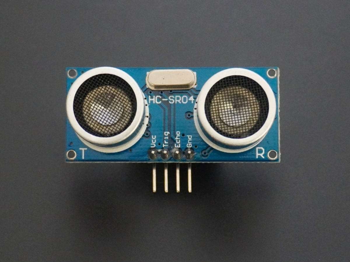
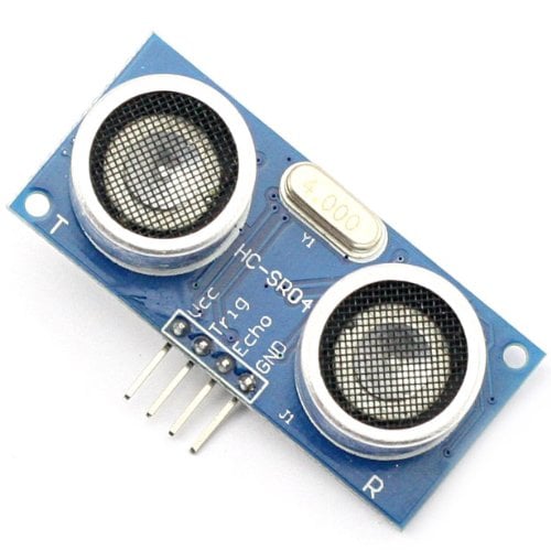
- Ultrasonic Module HC-SR04 works on the principle of SONAR and RADAR system.
- HC-SR-04 module has an ultrasonic transmitter, receiver, and control circuit on a single board.
- The module has only 4 pins, Vcc, Gnd, Trig, and Echo.
- When a pulse of 10µsec or more is given to the Trig pin, 8 pulses of 40 kHz are generated. After this, the Echo pin is made high by the control circuit in the module.
- The echo pin remains high till it gets an echo signal of the transmitted pulses back.
- The time for which the echo pin remains high, i.e. the width of the Echo pin gives the time taken for generated ultrasonic sound to travel towards the object and return.
- Using this time and the speed of sound in air, we can find the distance of the object using a simple formula for distance using speed and time.
For more information about ultrasonic module HC-SR04 and how to use it, refer to the topic Ultrasonic Module HC-SR04 in the sensors and modules section.
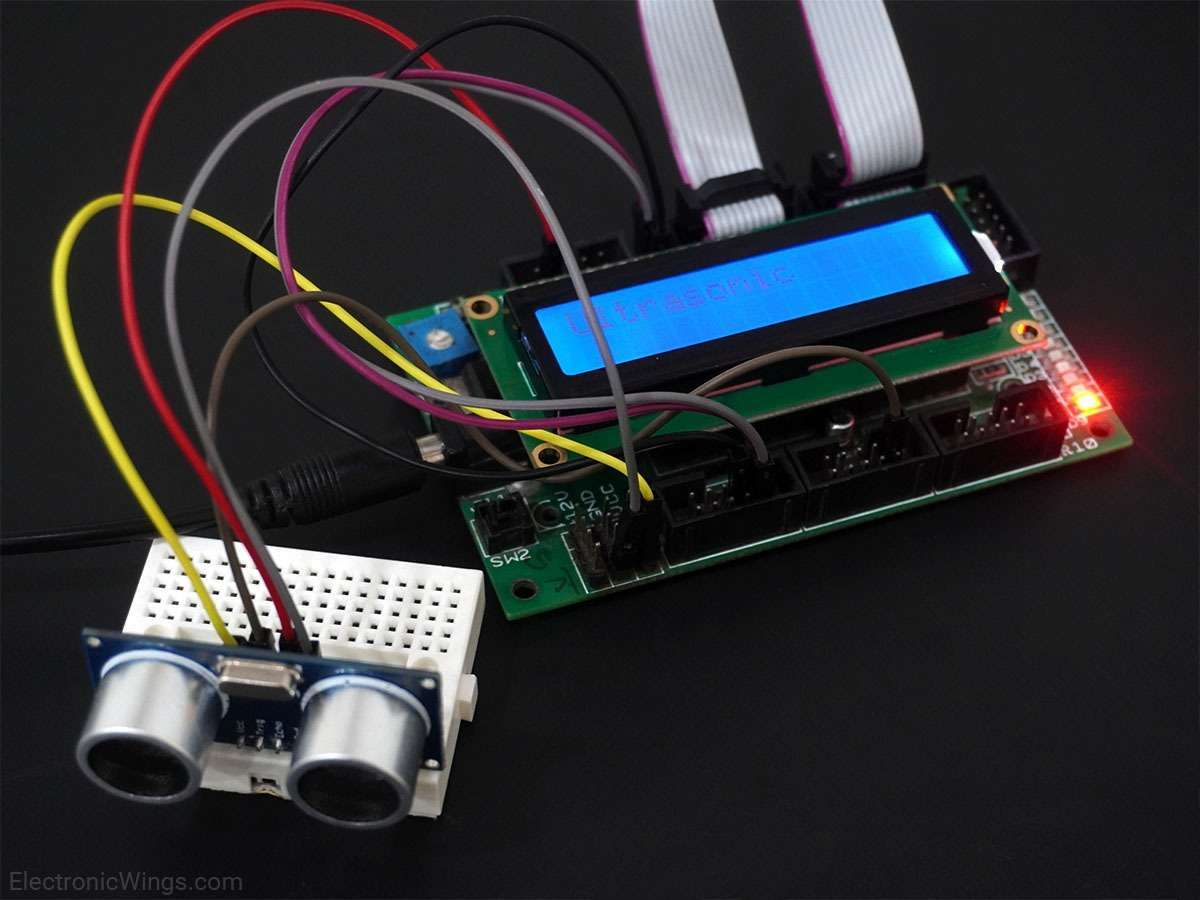
Connection Diagram of Ultrasonic Sensor HC-SR04 with ATmega16/32
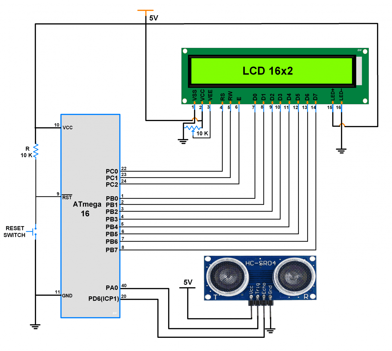
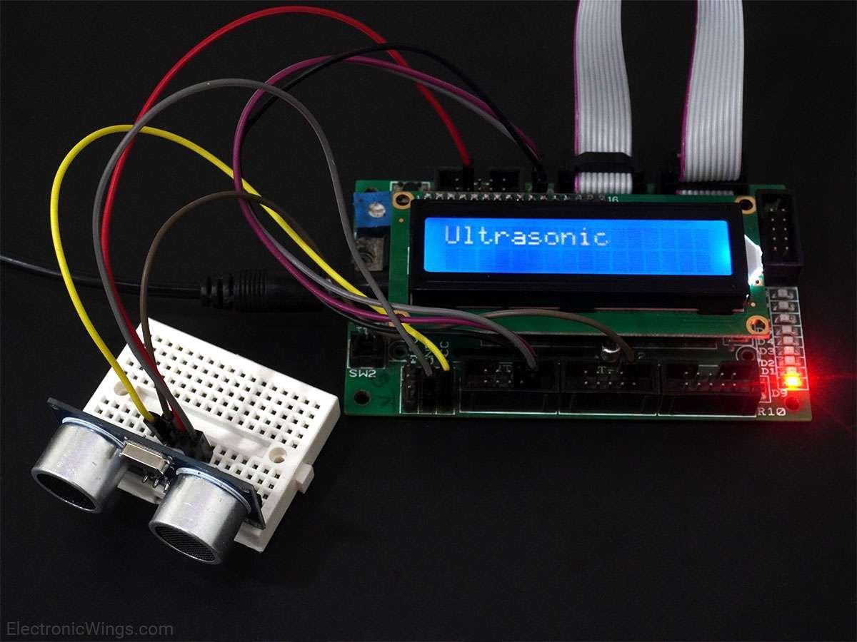
Measure Distance and Print on LCD16x2 using Ultrasonic Sensor and Atmega16 Microcontroller
Let’s design an application in which we will find the distance to an object by interfacing ultrasonic module HC-SR04 with AVR ATmega16 and display the distance on 16x2 LCD.
Steps of Programming
- ATmega16 microcontroller needs to transmit at least 10 us trigger pulse to the HC-SR04 Trig Pin.
- After getting a trigger pulse, HC-SR04 automatically sends eight 40 kHz sound waves and the microcontroller waits for rising edge output at the Echo pin.
- When the rising edge capture occurs at the Echo pin which is connected to an input of ATmega16, start Timer of ATmega16 and again wait for a falling edge on the Echo pin.
- As soon as the falling edge is captured at the Echo pin, the microcontroller reads the count of the Timer. This time count is used to calculate the distance to an object.
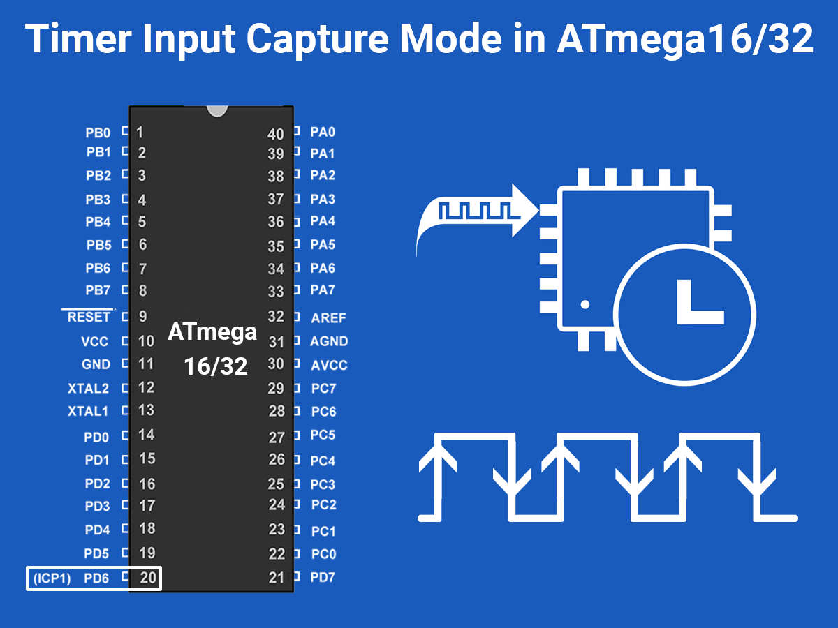
Here we are using the input capture mode of ATmega16 on PD6(ICP1) pin as shown in the above interfacing diagram.
Calculation (distance in cm) (H1)
Sound velocity = 343.00 m/s = 34300 cm/s
The distance of Object (in cm) =
=
=
Now, here we have selected an internal 8 MHz oscillator frequency for ATmega16, with No-presale for timer frequency. Then time to execute 1 instruction is 0.125 us.
So, the timer gets incremented after 0.125 us time elapse.
= 17150 x (TIMER value) x 0.125 x 10^-6 cm
= 0.125 x (TIMER value)/58.30 cm
= (TIMER value) / 466.47 cm
Ultrasonic Sensor HC-SR04 Code for ATmega16/32
/*
 * Ultrasonic sensor HC-05 interfacing with AVR ATmega16
 * http://www.electronicwings.com
 */

#define F_CPU 8000000UL
#include <avr/io.h>
#include <avr/interrupt.h>
#include <util/delay.h>
#include <string.h>
#include <stdlib.h>
#include "LCD_16x2_H_file.h"	/* Include LCD header file */

#define  Trigger_pin	PA0	/* Trigger pin */

int TimerOverflow = 0;

ISR(TIMER1_OVF_vect)
{
	TimerOverflow++;	/* Increment Timer Overflow count */
}

int main(void)
{
	char string[10];
	long count;
	double distance;

	DDRA = 0x01;		/* Make trigger pin as output */
	PORTD = 0xFF;		/* Turn on Pull-up */

	LCD_Init();
	LCD_String_xy(1, 0, "Ultrasonic");

	sei();			/* Enable global interrupt */
	TIMSK = (1 << TOIE1);	/* Enable Timer1 overflow interrupts */
	TCCR1A = 0;		/* Set all bit to zero Normal operation */

	while(1)
	{
		/* Give 10us trigger pulse on trig. pin to HC-SR04 */
		PORTA |= (1 << Trigger_pin);
		_delay_us(10);
		PORTA &= (~(1 << Trigger_pin));

		TCNT1 = 0;	/* Clear Timer counter */
		TCCR1B = 0x41;	/* Capture on rising edge, No prescaler*/
		TIFR = 1<<ICF1;	/* Clear ICP flag (Input Capture flag) */
		TIFR = 1<<TOV1;	/* Clear Timer Overflow flag */

		/*Calculate width of Echo by Input Capture (ICP) */

		while ((TIFR & (1 << ICF1)) == 0);/* Wait for rising edge */
		TCNT1 = 0;	/* Clear Timer counter */
		TCCR1B = 0x01;	/* Capture on falling edge, No prescaler */
		TIFR = 1<<ICF1;	/* Clear ICP flag (Input Capture flag) */
		TIFR = 1<<TOV1;	/* Clear Timer Overflow flag */
		TimerOverflow = 0;/* Clear Timer overflow count */

		while ((TIFR & (1 << ICF1)) == 0);/* Wait for falling edge */
		count = ICR1 + (65535 * TimerOverflow);	/* Take count */
		/* 8MHz Timer freq, sound speed =343 m/s */
		distance = (double)count / 466.47;

		dtostrf(distance, 2, 2, string);/* distance to string */
		strcat(string, " cm   ");	/* Concat unit i.e.cm */
		LCD_String_xy(2, 0, "Dist = ");
		LCD_String_xy(2, 7, string);	/* Print distance */
		_delay_ms(200);
	}
}
Video of Distance Measurement using Ultrasonic Sensor and Atmega16 Microcontroller
Components Used
Powered by
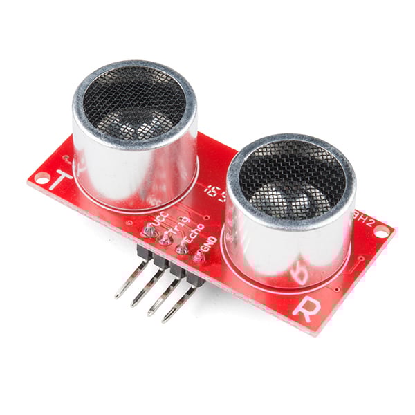
Ultrasonic module HC-SR04 is generally used for finding distance value and obstacle detection. It can operate in the range 2cm-400cm.
474-SEN-15569
Downloads
Comments51
Join the discussion — share a question or tip.
- SA
I tested this program. It is accurate below 1 meter, but it does not show above 1 meter at all. (The number displayed on the LCD does not go beyond 100 centimeters). Why?
- DK
Hello Sir, I downloaded the project file you provided, but it's not functioning correctly on my end. The display only shows "Ultrasonic Dist" with "Ultrasonic" in the first row and "Dist" in the second row. According to the project requirements, it should show the full word "Distance" followed by the measured distance from the ultrasonic sensor. I also have a question regarding the compatibility of the ultrasonic sensor with an ATmega32 using an external 16 MHz crystal clock frequency. I'm working in Microchip Studio 7 and Proteus 8 Professional. I’ve set up the hardware as well, but the results remain the same. Could you please assist with resolving this issue? Thank you.
- MU
where did you come up with number 466.47 in distance calculation, I calculate according to your formula but I didn't get the value you get
- AA
There are some issue coming while running the code
- AB
Thanks for the project. How can I see the return and received frequency value?
- AK
I am using ATMEGA8 and connect Trig to PC0(23no pin) and Echo to PB0/IPC1(14 no pin) . Its not showing distance , but when I touch the Trig pin then show wrong distance with alphabet 'E'. please help me...
- ALALIUZAIRMEHDI· edited
Data on the slave side is not appearing on LCD? any solution?
- LI
Severity Code Description Project File Line Error LCD_16x2_H_file.h: No such file or directory EP_Ultrasonic_Sensor c:\users\lijin\Documents\Atmel Studio\7.0\EP_Ultrasonic_Sensor\EP_Ultrasonic_Sensor\main.c 20 from where get header file
- YA
can we use these timer again for another device
- YA
can we use these timer again for another device
- AS
hello sir a question i do not have include "LCD_16x2_H_file.h" what should i do ?
- SN
Thank you for your tutorial. It helps me so much. I wonder what if I use PD4 pin or other pins instead of PD6. Does the circuit work correctly?
- MA
Thank you very much, but please help me what is Timer Overflow = 0 for ? and why we must use (65535 * Timer Overflow) ?
- MI
Hi nice project, tell me pls.. what is 466.47 and how did you calculate it?
- JU
What if I want to use 2 HC-SR04? (A front sensor and a rear sensor). In my case I'm using the ATmega16 which only has one Input Capture Pin. I'm connecting both echoes to that pin and just triggering one sensor at a time, never both simultaneously, and somehow the echo pulse of both sensors can't be detected.
- RA
HC-SR04 is same with HC-SR05?
- RA
i got warning massage /************************************************ CodeVisionAVR C Compiler V3.0 (C) 1998-2012 Pavel Haiduc, HP InfoTech S.R.L. AVR Interrupt support and Atmel Studio 6 compatibility macros/functions. ************************************************/ #ifndef _INTERRUPT_INCLUDED_ #define _INTERRUPT_INCLUDED_ #include <io.h> #define sei() #asm("sei") #define cli() #asm("cli") #define __enable_interrupt() #asm("sei") #define __disable_interrupt() #asm("cli") #define cpu_irq_enable() #asm("sei") #define cpu_irq_disable() #asm("cli") #define ISR(vector) interrupt [vector] void __isr##vector (void) typedef unsigned char irqflags_t; static inline unsigned char cpu_irq_save(void) { irqflags_t flags = SREG; __disable_interrupt(); return flags; } #define cpu_irq_restore(flags) {SREG = flags;} #ifdef _ATXMEGA_DEVICE_ #define irq_initialize_vectors() {PMIC.CTRL = PMIC_LOLVLEN_bm | PMIC_MEDLVLEN_bm | PMIC_HILVLEN_bm;} #define cpu_irq_is_enabled_flags(flags) (flags & CPU_I_bm); #else #define cpu_irq_is_enabled_flags(flags) (flags & (1<<SREG_I)); #endif #define cpu_irq_is_enabled() cpu_irq_is_enabled_flags(SREG) #endif and the warning in __disable_interrupt(); can u solve that?
- SA
Error is coming for LCD library function
- JW
Hi, I'm trying to incorporate an ultrasonic sensor into a project that is using ATmega 1284s. I made changes such as TIFR to TIFR0 which allowed this code to compile correctly, but I can't get the sensor to work. I'm not trying to measure variable distances. I just want to set a flag if an object is at or within 20cm of the sensor. For whatever reason though, the distance variable is not being updated. I'd appreciate any help you can give me
- BI
hii i am using the Atmega32. what should i change? it is very important for me. plz help me with short time thank you
- BI
Replying to @lokeshc
thank u. in interface, im using the buzzer. if obstacle is in 60cm, buzzer should start ring. for this, what should i change, thank you for ur great help
- SA
Hello Sir Firstly, thank you very much for this project. how can I use two ultrasonic sensors to measure the distance between then at the same time and compare then. Thanks in advance
- KE
Hi sir, you are wonderful person i respect you and your work. I have two question the first the "TimerOverflow" should be volatile, second at this part of your program TCNT1 = 0; /* Clear Timer counter */ TCCR1B = 0x01; /* Capture on falling edge, No prescaler */ TIFR = 1<<ICF1; /* Clear ICP flag (Input Capture flag) */ TIFR = 1<<TOV1; /* Clear Timer Overflow flag */ TimerOverflow = 0;/* Clear Timer overflow count */ why you make TimerOverflow = 0, i don't get it if it was 2 and then you make it 0 when you use this equation "count = ICR1 + (65535 * TimerOverflow);" The TimerOverflow will be zero.
- SU
the correct distance is only 70 cm why? according to its datasheet up to 400 cm we can measure but unable to get the correct measure. I have used external crystal 16Mhz with atmega32, it counts the distance up to 70 cm correctly and if the distance >70 again it show 2/3 cm . I mean it is working in the range of 70 cm for me. how to solve it
- SH
Hi, I also got the same problem. After spending nearly 4 hrs, I found that there is a bug in the code. It is not related to clock frequency. Problem is as soon as Timer overflows (in case of 16MHz freq. timer overflow occur at 70cm distance) TimerOverflow variable is not updating. Due to this error is there in distance measurement over 70cm. You can overcome or remove this bug by declaring TimerOverflow as "volatile" or "volatile int TimerOverflow = 0;" . This will solve this issue.
- TH
it Count in 2 Register 16 Bit So 2^16 = 65535