ADC in AVR ATmega16/ATmega32
AVR ATmega16/ATmega32 has an inbuilt 10-bit ADC (Analog to Digital Converter) to convert Analog voltage to a digital value.
Introduction to ATmega ADC
ADC (Analog to Digital converter) is the most widely used device in embedded systems which is designed especially for data acquisition. In the AVR ATmega series normally 10-bit ADC is inbuilt in the controller.
Let us see how to use the ADC of AVR ATmega16 / ATmega32.
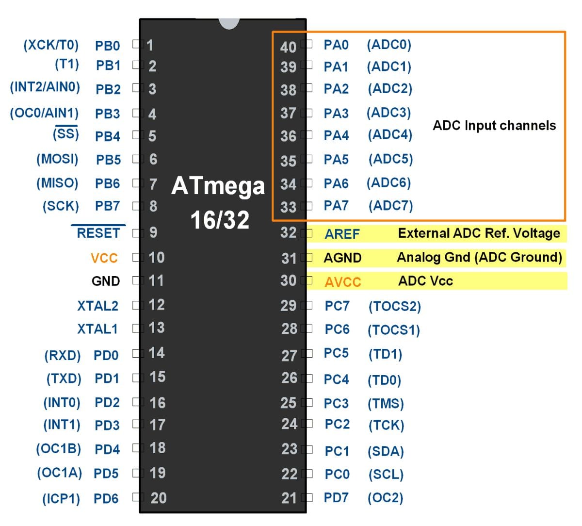
ATmega16/32 supports eight ADC channels, which means we can connect eight analog inputs at a time. ADC channel 0 to channel 7 are present on PORTA. i.e. Pin no.33 to 40.
The controller has 10 bit ADC, which means we will get digital output 0 to 1023.
i.e. When the input is 0V, the digital output will be 0V & when input is 5V (and Vref=5V), we will get the highest digital output corresponding to 1023 steps, which is 5V.
So controller ADC has 1023 steps and
- Step size with Vref=5V : 5/1023 = 4.88 mV.
- Step size with Vref=2.56 : 2.56/1023 = 2.5 mV.
So Digital data output will be Dout = Vin / step size.
ATmega16/32 ADC Features
- It is 10-bit ADC
- Converted output binary data is held in two special functions 8-bit register ADCL (result Low) and ADCH (result in High).
- ADC gives 10-bit output, so (ADCH: ADCL) only 10-bits are useful out of 16-bits.
- We have options to use this 10-bits as upper bits or lower bits.
- We also have three options for Vref. 1. AVcc (analog Vcc), 2. Internal 2.56 v3. External Aref. Pin.
- The total conversion time depends on crystal frequency and ADPS0: 2 (frequency devisor)
- If you decided to use AVcc or Vref pin as ADC voltage reference, you can make it more stable and increase the precision of ADC by connecting a capacitor between that pin and GND.
ATmega16/32 ADC Registers
In AVR ADC, we need to understand four main register -
- ADCH: Holds digital converted data higher byte
- ADCL: Holds digital converted data lower byte
- ADMUX: ADC Multiplexer selection register
- ADCSRA: ADC Control and status register
ADCH: ADCL register
First, two-register holds the digital converted data, which is 10-bit.
ADMUX Register

Bit 7: 6 – REFS1 : 0: Reference Selection Bits
Reference voltage selection for ADC
| REFS1 | REFS0 | Vref to ADC |
|---|---|---|
| 0 | 0 | AREF pin |
| 0 | 1 | AVCC pin i.e. Vcc 5 V |
| 1 | 0 | Reserved |
| 1 | 1 | Internal 2 |
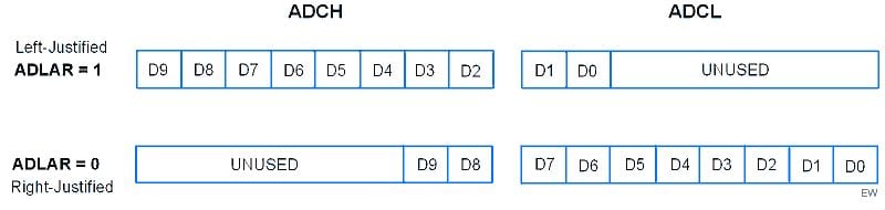
Bit 5 – ADLAR: ADC Left Adjust Result
Use 10-bits output as upper bits or lower bits in ADCH & ADCL.
Bits 4 : 0 – MUX4 : 0: Analog Channel and Gain Selection Bits
We can select input channel ADC0 to ADC7 by using these bits. These bits are also used to select comparator (inbuilt in AVR) inputs with various gain. We will cover these comparator operations in another part.
Selecting a channel is very easy, just put the channel number in MUX4 : 0.
Suppose you are connecting the input to ADC channel 2 then put 00010 in MUX4 : 0.
Suppose you are connecting the input to ADC channel 5 then put 00101 in MUX4 : 0.
ADCSRA Register:

- Bit 7 – ADEN: ADC Enable
Writing one to this bit enables the ADC. By writing it to zero, the ADC is turned off. Turning the ADC off while a conversion is in progress, will terminate this conversion.
- Bit 6 – ADSC: ADC Start Conversion
Writing one to this bit starts the conversion.
- Bit 5 – ADATE: ADC Auto Trigger Enable
Writing one to this bit, results in Auto Triggering of the ADC is enabled.
- Bit 4 – ADIF: ADC Interrupt Flag
This bit is set when an ADC conversion completes and the Data Registers are updated.
- Bit 3 – ADIE: ADC Interrupt Enable
Writing one to this bit, the ADC Conversion Complete Interrupt is activated.
- Bits 2 : 0 – ADPS2 : 0: ADC Prescaler Select Bits
These bits determine the division factor between the XTAL frequency and the input clock to the ADC
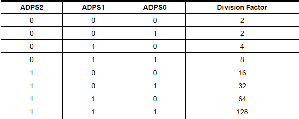
We can select any divisor and set frequency Fosc/2, Fosc/4, etc. for ADC, But in AVR, ADC requires an input clock frequency less than 200KHz for max. accuracy. So we have to always take care of not exceeding ADC frequency more than 200KHz.
Suppose your clock frequency of AVR is 8MHz, then we must have to use devisor 64 or 128. Because it gives 8MHz/64 = 125KHz, which is lesser than 200KHz.
ATmega16/32 ADC Interfacing Diagram
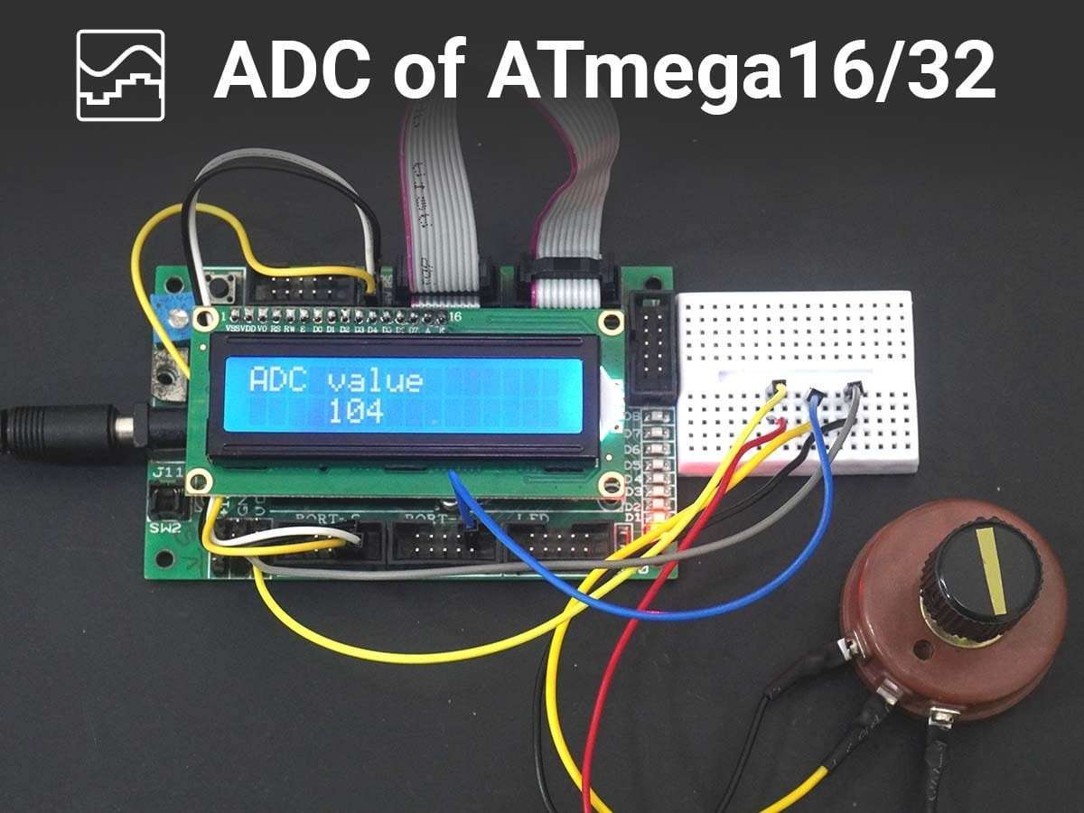
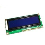
Here we are displaying ADC channel 0 values on the 16x2 LCD using ATmega16/32 Microcontroller
Steps to Program ATmega16/32 ADC
- Make the ADC channel pin as an input.
- Set ADC enable bit in ADCSRA, select the conversion speed using ADPS2 : 0. For example, we will select devisor 128.
- Select ADC reference voltage using REFS1: REFS0 in ADMUX register, for example, we will use AVcc as a reference voltage.
- Select the ADC input channel using MUX4 : 0 in ADMUX, for example, we will use channel 0.
- So our value in register ADCSRA = 0x87 and ADMUX = 0x40.
- Start conversion by setting bit ADSC in ADCSRA. E.g.ADCSRA |= (1<<ADSC);
- Wait for conversion to complete by polling ADIF bit in ADCSRA register.
- After the ADIF bit gone high, read ADCL and ADCH register to get digital output.
- Notice that read ADCL before ADCH; otherwise result will not be valid.
ATmega16/32 ADC Code
#define F_CPU 8000000UL
#include <avr/io.h>
#include <util/delay.h>
#include <stdlib.h>
#include "LCD_16x2_H.h"

void ADC_Init()
{
	DDRA=0x0;			/* Make ADC port as input */
	ADCSRA = 0x87;			/* Enable ADC, fr/128  */
	ADMUX = 0x40;			/* Vref: Avcc, ADC channel: 0 */

}

int ADC_Read(char channel)
{
	int Ain,AinLow;

	ADMUX=ADMUX|(channel & 0x0f);	/* Set input channel to read */

	ADCSRA |= (1<<ADSC);		/* Start conversion */
	while((ADCSRA&(1<<ADIF))==0);	/* Monitor end of conversion interrupt */

	_delay_us(10);
	AinLow = (int)ADCL;		/* Read lower byte*/
	Ain = (int)ADCH*256;		/* Read higher 2 bits and
					Multiply with weight */
	Ain = Ain + AinLow;
	return(Ain);			/* Return digital value*/
}


int main()
{
	char String[5];
	int value;

	ADC_Init();
	LCD_Init();			/* Initialization of LCD */
	LCD_String("ADC value");	/* Write string on 1st line of LCD */

	while(1)
	{

		LCD_Command(0xc4);	/* LCD16x2 cursor position */
		value=ADC_Read(0);	/* Read ADC channel 0 */
		itoa(value,String,10);	/* Integer to string conversion */
		LCD_String(String);
		LCD_String("  ");
	}
	return 0;
}
Video
Components Used
Powered by
Downloads
Comments16
Join the discussion — share a question or tip.
- AN
int ADC_Read(char channel) { ADMUX |= channel & 0x0f; ADCSRA |= 1<<ADSC; while((ADCSRA&(1<<ADIF))==0); _delay_us(10); //return((ADCH<<8)+ADCL); // doesn't work right return(ADCL+(ADCH<<8)); // works fine } Could anybody answer why? Thanks!
- AU
in 9th step of above program, it is given that read ADCL before ADCH; otherwise result will not be valid.
- HIhiteshpatidar20· edited
LCD_String(" "); how am i getting wrong output without using this function above what is the pupose of this function here?
- JO
how can i show factorial number like 230.5v in lcd using ur code ? pls help
- VI
sir, in adxl335 sensor , how to use three channel??
- CH
sir how a port start d7 pin our first pin and d0 the last pin. i want lcd data pin d7-d0 connect the pcb board plz tell me a example number send to the port and binary start from d7 pin
- VI
The code is not working with Simullide. Pls help
- SH
Hello sir , i have one query , how to convert float value to string by using dtostrf function , i follwed the syntax properly but still the flost value was not displayed
- AU
char * dtostrf( double __val, signed char __width, unsigned char __prec, char * __s) __width and __prec decides the output size and dot(.) position e.g. if __width is 7 and __prec is 3 then o/p will come as "000.000" __s is result buffer we have to pass to function. Note: keep always result buffer size > __width definition (referred from microchip website) : The dtostrf() function converts the double value passed in __val into an ASCII representation that will be stored under __s. The caller is responsible for providing sufficient storage in __s. Conversion is done in the format "[-]d.ddd". The minimum field __width of the output string (including the possible dot(.) and the possible sign for negative values ) is given in __width, and __prec determines the number of digits after the decimal sign. __width is signed value, negative for left adjustment. The dtostrf() function returns the pointer to the converted string __s.
- EM
how you do this schematics with avr?
- 36365ngay0khoc· edited
You can give me libraly LCD 16x2 , please!
- BO
Please which software do you use in drawing your diagrams shown above.