USART in AVR ATmega16/ATmega32
USART (Universal Synchronous Asynchronous Receiver Transmitter) which transfers the data bits serially. Using USART, we can communicate with the PC and serial UART devices like GSM module, GPS, etc.
Introduction
AVR ATmega has flexible USART, which can be used for serial communication with other devices like computers, serial GSM, GPS modules, etc.
Before beginning with AVR USART, we will walk through the basics of serial communication.
Serial data framing
While sending/receiving data, some bits are added for the purpose of knowing the beginning/ending of data, etc. commonly used structure is: 8 data bits, 1 start bit (logic 0), and 1 stop bit (logic 1), as shown:
.png)
There are also other supported frame formats available in UART, like parity bit, variable data bits (5-9 data bits).
Speed (Baud rate)
As we know the bit rate is “Number of bits per second (bps)”, also known as Baud rate in Binary system. Normally this defines how fast the serial line is. There are some standard baud rates defined e.g. 1200, 2400, 4800, 19200, 115200 bps, etc. Normally 9600 bps is used where speed is not a critical issue.
Wires and Hardware connection
Normally in USART, we only need Tx (Transmit), Rx(Receive), and GND wires.
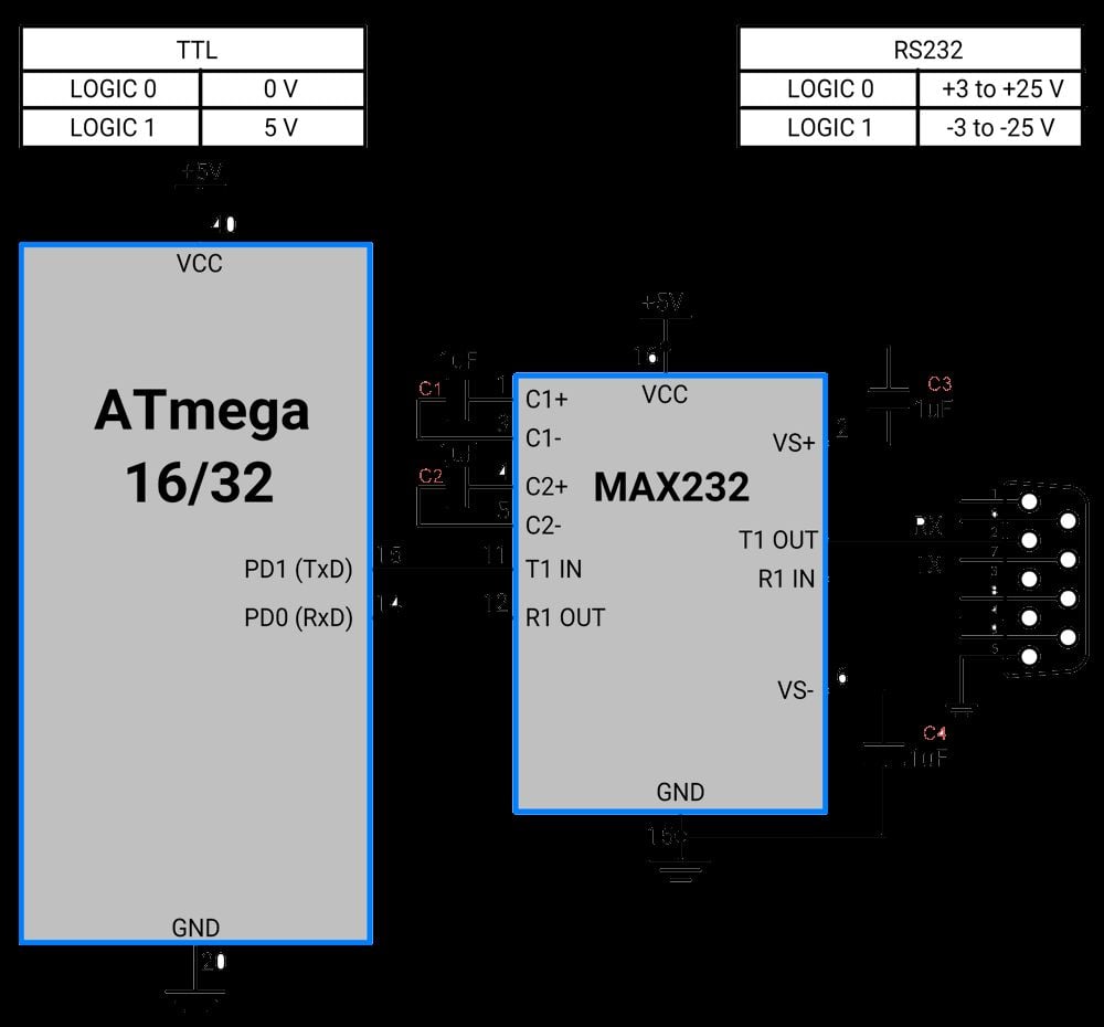
- AVR ATmega USART has a TTL voltage level which is 0 v for logic 0 and 5 v for logic 1.
- In computers and most of the old devices, RS232 protocol is used for serial communication, where normally 9 pin ‘D’ shape connector is used. RS232 serial communication has different voltage levels than ATmega serial communication i.e. +3 v to +25 v for logic zero and -3 v to -25 v for logic 1.
- So to communicate with RS232 protocol, we need to use a voltage level converter like MAX232 IC.
Although there are 9 pins in the DB9 connector, we don’t need to use all the pins. Only 2nd Tx(Transmit), 3rd Rx(Receive), and 5th GND pin need to be connected.
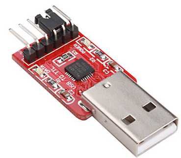
With a new PC and laptops, there is no RS232 protocol and DB9 connector. We have to use serial to the USB connector. There are various serial to USB connectors available e.g. CP2102, FT232RL, CH340, etc.
.jpg)
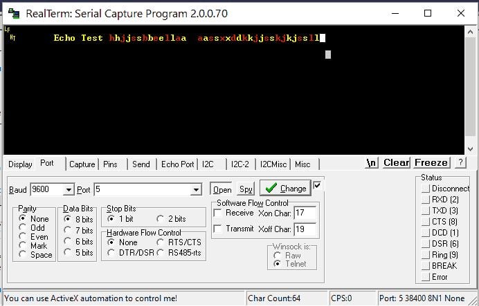
To see serial communication, we can use a serial terminal like Realterm, Teraterm, etc. By selecting the serial port number (COM port in windows) and baud rate, we can open a serial port for communication.
As stated in the datasheet ATmega 16 USART has the following features
- Full Duplex Operation (Independent Serial Receive and Transmit Registers)
- Asynchronous or Synchronous Operation
- Master or Slave Clocked Synchronous Operation
- High-Resolution Baud Rate Generator
- Supports Serial Frames with 5, 6, 7, 8, or 9 Data Bits and 1 or 2 Stop Bits
- Odd or Even Parity Generation and Parity Check Supported by Hardware
- Data OverRun Detection
- Framing Error Detection
- Noise Filtering Includes False Start Bit Detection and Digital Low Pass Filter
- Three Separate Interrupts on TX Complete, TX Data Register Empty, and RX Complete
- Multi-processor Communication Mode
- Double Speed Asynchronous Communication Mode
Programming of USART in AVR
To program, first, we need to understand the basic registers used for USART
AVR basic Registers
- UDR: USART Data Register
It has basically two registers, one is Tx. Byte and the other is Rx Byte. Both share the same UDR register. Do remember that, when we write to the UDR reg. Tx buffer will get written and when we read from this register, Rx Buffer will get read. Buffer uses the FIFO shift register to transmit the data.
2. UCSRA: USART Control and Status Register A. As the name suggests, is used for control and status flags. In a similar fashion, there are two more USART control and status registers, namely UCSRB and UCSRC.
3. UBRR: USART Baud Rate Register, this is a 16-bit register used for the setting baud rate.
We will see this register in detail:
UCSRA: USART Control and Status Register A

- Bit 7 – RXC: USART Receive Complete
This flag bit is set when there is unread data in UDR. The RXC Flag can be used to generate a Receive Complete interrupt.
- Bit 6 – TXC: USART Transmit Complete
This flag bit is set when the entire frame from Tx Buffer is shifted out and there is no new data currently present in the transmit buffer (UDR). The TXC Flag bit is automatically cleared when a transmit complete interrupt is executed, or it can be cleared by writing a one to its bit location. The TXC Flag can generate a Transmit Complete interrupt.
- Bit 5 – UDRE: USART Data Register Empty
If UDRE is one, the buffer is empty which indicates the transmit buffer (UDR) is ready to receive new data. The UDRE Flag can generate a Data Register Empty Interrupt. UDRE is set after a reset to indicate that the transmitter is ready.
- Bit 4 – FE: Frame Error
- Bit 3 – DOR: Data OverRun
This bit is set if a Data OverRun condition is detected. A Data OverRun occurs when the receive buffer is full (two characters) and a new character is waiting in the receive Shift Register.
- Bit 2 – PE: Parity Error
- Bit 1 – U2X: Double the USART Transmission Speed
- Bit 0 – MPCM: Multi-processor Communication Mode
UCSRB: USART Control and Status Register B

- Bit 7 – RXCIE: RX Complete Interrupt Enable
Writing one to this bit enables interrupt on the RXC Flag.
- Bit 6 – TXCIE: TX Complete Interrupt Enable
Writing one to this bit enables interrupt on the TXC Flag.
- Bit 5 – UDRIE: USART Data Register Empty Interrupt Enable
Writing one to this bit enables interrupt on the UDRE Flag.
- Bit 4 – RXEN: Receiver Enable
Writing one to this bit enables the USART Receiver.
- Bit 3 – TXEN: Transmitter Enable
Writing one to this bit enables the USART Transmitter.
- Bit 2 – UCSZ2: Character Size
The UCSZ2 bits combined with the UCSZ1:0 bit in UCSRC sets the number of data bits (Character Size) in a frame the receiver and transmitter use.
- Bit 1 – RXB8: Receive Data Bit 8
- Bit 0 – TXB8: Transmit Data Bit 8
UCSRC: USART Control and Status Register C

- Bit 7 – URSEL: Register Select
This bit selects between accessing the UCSRC or the UBRRH Register, as both register shares the same address. The URSEL must be one when writing the UCSRC or else data will be written in the UBRRH register.
- Bit 6 – UMSEL: USART Mode Select
This bit selects between the Asynchronous and Synchronous mode of operation.
0 = Asynchronous Operation
1 = Synchronous Operation
- Bit 5:4 – UPM1:0: Parity Mode
These bits enable and set the type of parity generation and check. If parity a mismatch is detected, the PE Flag in UCSRA will be set.
| UPM1 | UPM0 | Parity Mode |
|---|---|---|
| 0 | 0 | Disabled |
| 0 | 1 | Reserved |
| 1 | 0 | Enabled, Even Parity |
| 1 | 1 | Enabled, Odd Parity |
- Bit 3 – USBS: Stop Bit Select
This bit selects the number of Stop Bits to be inserted by the Transmitter. The Receiver ignores this setting.
0 = 1-bit
1 = 2-bit
- Bit 2:1 – UCSZ1:0: Character Size
The UCSZ1:0 bits combined with the UCSZ2 bit in UCSRB sets the number of data bits (Character Size) in a frame the Receiver and Transmitter use.
| UCSZ2 | UCSZ1 | UCSZ0 | Character Size |
|---|---|---|---|
| 0 | 0 | 0 | 5-bit |
| 0 | 0 | 1 | 6-bit |
| 0 | 1 | 0 | 7-bit |
| 0 | 1 | 1 | 8-bit |
| 1 | 0 | 0 | Reserved |
| 1 | 0 | 1 | Reserved |
| 1 | 1 | 0 | Reserved |
| 1 | 1 | 1 | 9-bit |
- Bit 0 – UCPOL: Clock Polarity
This bit is used for synchronous mode only. Write this bit to zero when the asynchronous mode is used.
UBRRL and UBRRH: USART Baud Rate Registers

- Bit 15 – URSEL: Register Select
This bit selects between accessing the UCSRC or the UBRRH Register, as both register shares the same address. The URSEL must be one when writing the UCSRC or else data will be written in the UBRRH register.
- Bit 11:0 – UBRR11:0: USART Baud Rate Register.
Used to define the baud rate
Example: suppose Fosc=8 MHz and required baud rate= 9600 bps.
Then the value of UBRR= 51.088 i.e. 51.
We can also set this value by c code using pre-processor macro as follow.
#define F_CPU 8000000UL		/* Define frequency here its 8MHz */
#define USART_BAUDRATE 9600
#define BAUD_PRESCALE (((F_CPU / (USART_BAUDRATE * 16UL))) - 1)
BAUD_PRESCALE is the value that we have to load in the UBRR register to set the defined baud rate.
Programming steps
Initialization of USART
- Enable transmission and reception by using the UCSRB register.
- Set data bit size to 8 bit by using the UCSRC register.
- Set baud rate using the UBRR register.
void UART_init(long USART_BAUDRATE)
{
	UCSRB |= (1 << RXEN) | (1 << TXEN);	/* Turn on transmission and reception */
	UCSRC |= (1 << URSEL) | (1 << UCSZ0) | (1 << UCSZ1);/* Use 8-bit char size */
	UBRRL = BAUD_PRESCALE;			/* Load lower 8-bits of the baud rate */
	UBRRH = (BAUD_PRESCALE >> 8);		/* Load upper 8-bits*/
}
Receiving Character
Monitor the RXC bit in UCSRA. RXC bit indicates receive complete status.
unsigned char UART_RxChar()
{
	while ((UCSRA & (1 << RXC)) == 0);/* Wait till data is received */
	return(UDR);		/* Return the byte */
}
Transmitting Character
Monitor the UDRE bit from UCSRA. When the UDRE flag becomes one, which indicates the transmitting buffer is empty and ready to accept another byte.
void UART_TxChar(char ch)
{
	while (! (UCSRA & (1<<UDRE)));  /* Wait for empty transmit buffer */
	UDR = ch ;
}
ATmega16/32 UART Serial Communication Code
Program for echo test. In this program, the ATmega 16 controller will receive a character and send it back. We can use the PC terminal to observe echo.
/*
	ATmega 16 UART echo program
	http://www.electronicwings.com
*/

#define F_CPU 8000000UL			/* Define frequency here its 8MHz */
#include <avr/io.h>
#include <util/delay.h>
#include <stdlib.h>
#include <stdio.h>

//#define USART_BAUDRATE 9600
#define BAUD_PRESCALE (((F_CPU / (USART_BAUDRATE * 16UL))) - 1)


void UART_init(long USART_BAUDRATE)
{
	UCSRB |= (1 << RXEN) | (1 << TXEN);/* Turn on transmission and reception */
	UCSRC |= (1 << URSEL) | (1 << UCSZ0) | (1 << UCSZ1);/* Use 8-bit character sizes */
	UBRRL = BAUD_PRESCALE;		/* Load lower 8-bits of the baud rate value */
	UBRRH = (BAUD_PRESCALE >> 8);	/* Load upper 8-bits*/
}

unsigned char UART_RxChar()
{
	while ((UCSRA & (1 << RXC)) == 0);/* Wait till data is received */
	return(UDR);			/* Return the byte*/
}

void UART_TxChar(char ch)
{
	while (! (UCSRA & (1<<UDRE)));	/* Wait for empty transmit buffer*/
	UDR = ch ;
}

void UART_SendString(char *str)
{
	unsigned char j=0;

	while (str[j]!=0)		/* Send string till null */
	{
		UART_TxChar(str[j]);
		j++;
	}
}

int main()
{
	char c;
	UART_init(9600);

	UART_SendString("\n\t Echo Test ");
	while(1)
	{
		c=UART_RxChar();
		UART_TxChar(c);
	}
}
We can connect ATmega controller’s serial communication pins to serial to USB converter module. Open serial communication port in PC by using any application e.g. RealTerm, Teraterm etc.
Serial Interrupt
Programming AVR Serial communication using Interrupt
Up till now, we have seen serial programming using the polling method, which wastes the time of the controller.
To enable interrupt-based transmission we have to set HIGH the USART Data Register Empty Interrupt Enable (UDRIE).
To enable interrupt-based reception we need to set HIGH the Receive Complete Interrupt Enable(RXCIE) bit in UCSRB.
ATmega16/32 UART Serial Communication Code using Interrupt
Receiving data using interrupt: Receive data and put it on PORTB continuously
/*

	ATmega 16 UART using interrupt
	http://www.electronicwings.com

*/

#define F_CPU 8000000UL			/* Define frequency here its 8MHz */
#include <avr/io.h>
#include <avr/interrupt.h>

#define BAUD_PRESCALE (((F_CPU / (USART_BAUDRATE * 16UL))) - 1)


void UART_init(long USART_BAUDRATE)
{
	UCSRB |= (1 << RXEN) | (1 << RXCIE);/* Turn on the transmission and reception */
	UCSRC |= (1 << URSEL) | (1 << UCSZ0) | (1 << UCSZ1);/* Use 8-bit character sizes */

	UBRRL = BAUD_PRESCALE;		/* Load lower 8-bits of the baud rate */
	UBRRH = (BAUD_PRESCALE >> 8);	/* Load upper 8-bits */
}

ISR(USART_RXC_vect)
{
	PORTB=UDR;
}

int main()
{
	UART_init(9600);
	sei();
	DDRB=0xFF;
	while(1);
}
Components Used
Powered by
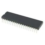
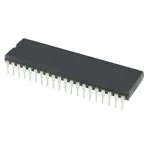

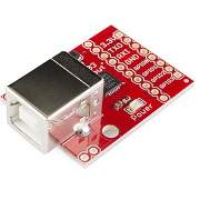
CP2103 is single chip USB to UART Bridge. It supports USB 2.0 protocol.
634-CP2103-GMR
Downloads
Comments25
Join the discussion — share a question or tip.
- PR
hello i was using you code with atmga32/atmega32a with internal frq 8mhz as i am receiving the char but it is garbage i have connected controller pin with ttl to usb convertor but still no output the fuse bit is set to low fuse E4 high fuse D9
- HI
Sir, please help me. I want to output the text received via usart to lcd 12864 from your early projects.I can't output the received (Char) using the GLCD_String(0,*char) function. I ask for help how can I solve this problem
- CL
Will it work for atmega 32 ? I was getting message like undeclaration.
- GO
Some people use Queue structures for serial interrupt how can we use it
- SH
UART AND USART IS A SAME THING IR DIFFERENT
- MU
different. uart is a subset of usart
- AW
Write a program to initialize UART to transmit and receive data at 19200bps with 8 data bits, odd parity and 1 stop bit. Assume system clock to be 3.6864MHz.
- AL
Sir, how can I send to the usart the temperature readings from the ADC. Let's say the variable Float tempC contains que value of the temperature reading, in C°, from an lm34, and I want to send those values to the USART. Could you please help me? Cheers in advanced.
- MU
use interrupt mode of usart
- SA
I need urgent help, I used the exact first code but my atmega32a only prints B0 or Nul in the terminal. Please urgent help is required.
- AL
Replying to @lokeshc
Sir, how can I send to the usart the temperature readings from the ADC. Let's say the variable Float tempC contains que value of the temperature reading, in C°, from an lm34, and I want to send those values to the USART. Could you please help me? Cheers in advanced
- TA
CAN WE DO THE SAME CONNECTIONS AND THE COMPONENTS VALUE FO ATMEGA328-P??
- MU
you have to include a char '0' in almost all the naming including registers and bits. Ex: UCSRA is called UCSR0A FE is called FE0 refer a datasheet for accurate naming.
- SU
Hi, can a similar approach be used to interface an ATMEGA32 with a WISOL SFM10R1 module ?
- LO
@SeKay003: Is this configuration valid for all microcontrollers? This is your query if I am not wrong Many AVR family microcontroller are compatible to each other. So, with lesser change in configuration will work for other avr microcontroller but not controller from another family or vendor.
- VI
Sir, How to receive an entire string in microcontroller and echo the same string using usart?
- VI
Replying to @lokeshc
Then, every string ends with '\n'. Can we use that? Thanks for reply...