Servo Motor Interfacing with AVR ATmega16
Servo motor is an electromechanical device that consists of Motor, Gear assembly, and feedback circuitry. It is used in Robotics applications, airplanes, rudders, quadcopters, etc.
Overview of Servo Motor
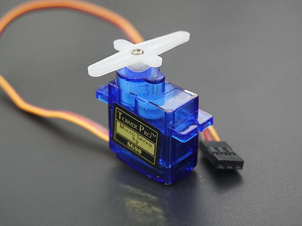
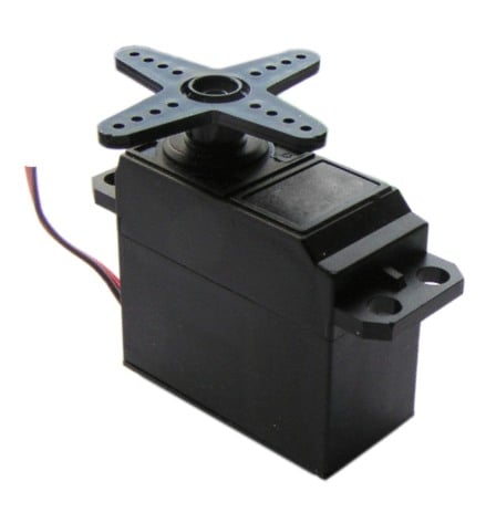
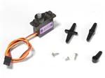
A servo motor is an electric device used for precise control of angular rotation. It is used where precise control is required, like in the case of control of a robotic arm.
It consists of a suitable motor with control circuitry for precise position control of the motor shaft.
It is a closed-loop system.
The rotation angle of the servo motor is controlled by applying a PWM signal to it.
By varying the width of the PWM signal, we can change the rotation angle and direction of the motor.
For more information about Servo Motor and how to use it, refer to the topic Servo Motor in the sensors and modules section.
For information about PWM in AVR ATmega16, refer the topic PWM in AVR ATmega16/ATmega32 in the ATmega inside section.
SG90 servo motor practical duty cycle time for -90° to +90 rotation.
At ~0.52ms duty cycle we get shaft position at -90° of its rotation.
At ~1.4ms duty cycle we get shaft position at 0° (neutral) of its rotation.
At ~2.4ms duty cycle we get shaft position at +90° of its rotation.
Generate PWM using AVR ATmega16
To control the servo motor in between -90° to +90° rotation. We need to generate a PWM waveform of 50Hz with duty cycle variation from ~0.5ms to ~2.4ms. We can use a fast PWM mode of ATmega16 using Timer1.
- Here we are generating PWM on the PD5/OC1A pin of ATmega16.
- We are using the 14th waveform generation mode of Timer1 in ATmega16, where TOP value for timer1 is decided by the ICR1 register i.e. we can load TOP value in the ICR1 register, where timer1 overflow occurs and timer1 overflow flag gets set.
- We have used internal 8MHz clock frequency and FOSC/64 clock for timer1 i.e. we set 8MHz/64 = 125KHz clock for timer1.
- Now Fast PWM frequency formula is
FPWM = FOSC / ( N * ( 1 + TOP ) )
Where N is pre-scaler divider i.e. 1, 8, 64, 256, or 1024.
- Hence to get 50Hz PWM frequency we need to load TOP value as 2499 so we get PWM frequency as,
FPWM = 8000000 / ( 64 * ( 1 + 2499 ) )
- So here we are loading ICR1 = 2499.
- Now just load OCR1A register values to get a compare match at the desired duty cycle.
- As here Timer1 clock is of 125KHz we get a one-timer count of 1/125 kHz = 8 us time period.
- Now suppose we want a PWM duty cycle period of 1ms as shown in the above figure, then we need to load the OCR1A register with 1ms/8us i.e. OCR1A = 125.
- So load OCR1A register as per duty cycle period requirement.
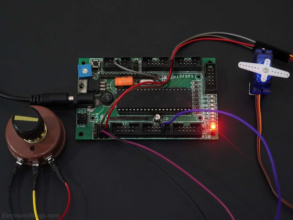
Connection Diagram of Micro Servo Motor SG90 with ATmega16/32
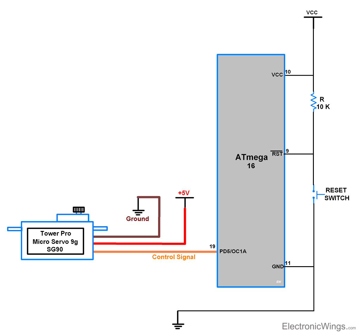
Rotate Servo Motor SG90 using Atmega16/32
Now let’s program AVR ATmega16 to generate 50Hz PWM to control Servo Motor in an angle between -90° to +90° rotation.
- For SG90 Micro servo motor, here we get practically -90° at 0.52ms duty cycle Period of 50Hz PWM, so we are going to load OCR1A = 65.
- After 0° at 1.4ms duty cycle Period of 50Hz PWM, so we are going to load OCR1A = 175.
- And +90° at 2.4ms duty cycle Period of 50Hz PWM, so we are going to load OCR1A = 300.
Servo Motor SG90 Code for Atmega16/32
/*
 * ATmega16_Servo_Motor
 * http://www.electronicwings.com
 */

#define F_CPU 8000000UL		/* Define CPU Frequency e.g. here its 8MHz */
#include <avr/io.h>			/* Include AVR std. library file */
#include <stdio.h>			/* Include std. library file */
#include <util/delay.h>		/* Include Delay header file */

int main(void)
{
	DDRD |= (1<<PD5);	/* Make OC1A pin as output */
	TCNT1 = 0;			/* Set timer1 count zero */
	ICR1 = 2499;		/* Set TOP count for timer1 in ICR1 register */

	/* Set Fast PWM, TOP in ICR1, Clear OC1A on compare match, clk/64 */
	TCCR1A = (1<<WGM11)|(1<<COM1A1);
	TCCR1B = (1<<WGM12)|(1<<WGM13)|(1<<CS10)|(1<<CS11);
	while(1)
	{
		OCR1A = 65;		/* Set servo shaft at -90° position */
		_delay_ms(1500);
		OCR1A = 175;	/* Set servo shaft at 0° position */
		_delay_ms(1500);
		OCR1A = 300;	/* Set servo at +90° position */
		_delay_ms(1500);
	}
}
Control the Servo Motor by using Potentiometer With ATmega16/32
Now let’s program AVR ATmega16 to generate 50Hz PWM to control Servo Motor in an angle between -90° to +90° rotation using an external potentiometer knob.
- Here we are using ADC channel 0 of ATmega16 to read the external potentiometer knob and according to the ADC value we are varying the OCR1A register value in between 65 to 300
- Refer ADC in AVR ATmega16/ATmega32 for more information on ADC in ATmega16.
Connection Diagram of Servo Motor SG90 and Potentiometer with ATmega16/32
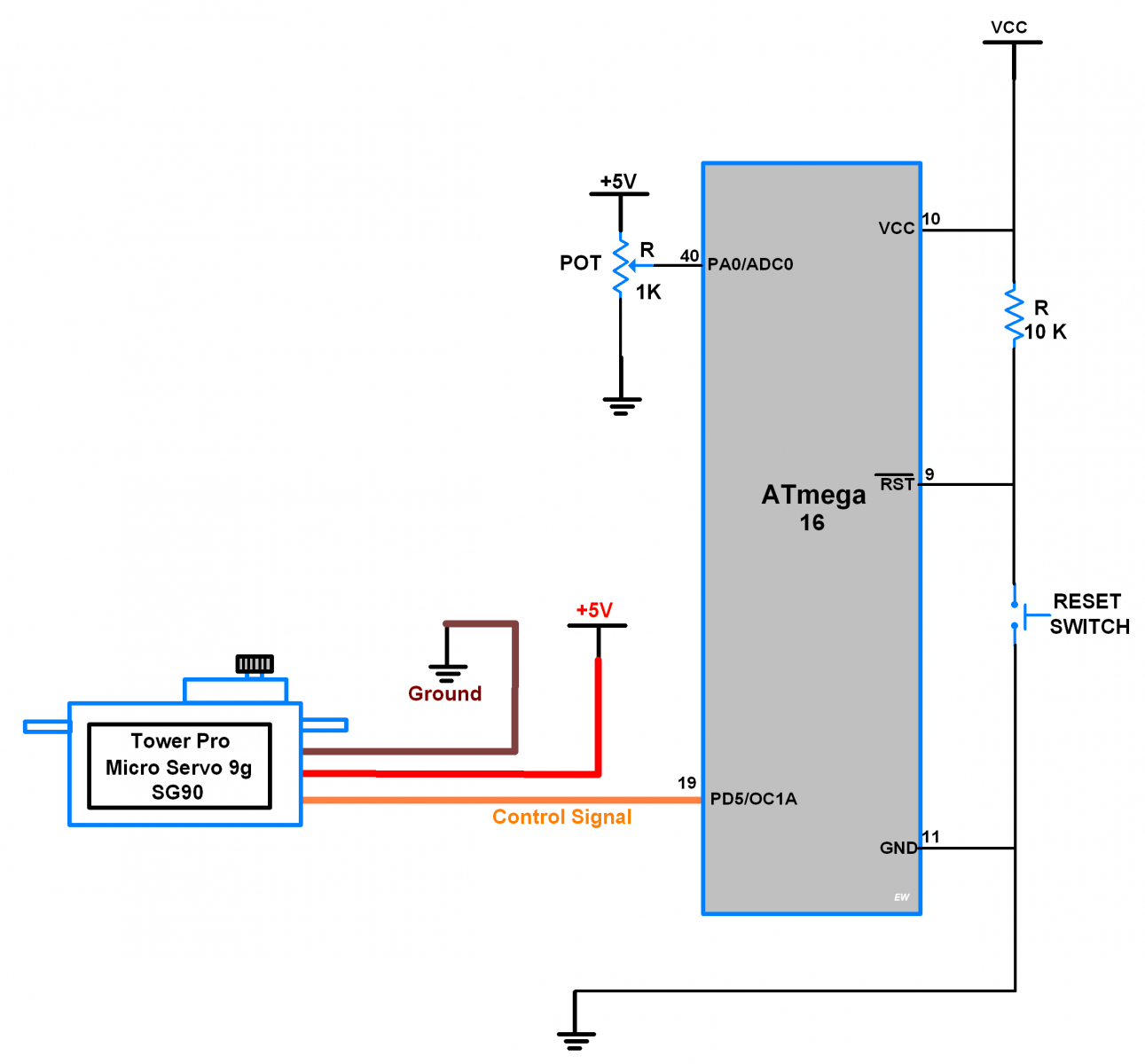
Potentiometer Controlled Servo Motor Code for ATmega16/32
/*
 * ATmega16_Servo_Motor.c
 * http://www.electronicwings.com
 */

#define F_CPU 8000000UL		/* Define CPU Frequency e.g. here its 8MHz */
#include <avr/io.h>			/* Include AVR std. library file */
#include <stdio.h>			/* Include std. library file */
#include <util/delay.h>		/* Include Delay header file */

void ADC_Init()				/* ADC Initialization function */
{
	DDRA=0x00;				/* Make ADC port as input */
	ADCSRA = 0x87;			/* Enable ADC, with freq/128  */
	ADMUX = 0x40;			/* Vref: Avcc, ADC channel: 0 */
}

int ADC_Read(char channel)	/* ADC Read function */
{
	ADMUX = 0x40 | (channel & 0x07);	/* set input channel to read */
	ADCSRA |= (1<<ADSC);				/* Start ADC conversion */

	/* Wait until end of conversion by polling ADC interrupt flag */
	while (!(ADCSRA & (1<<ADIF)));
	ADCSRA |= (1<<ADIF);	/* Clear interrupt flag */
	_delay_ms(1);			/* Wait a little bit */
	return ADCW;			/* Return ADC word */
}

int main(void)
{
	ADC_Init();			/* Initialize ADC */
	DDRD |= (1<<PD5);	/* Make OC1A pin as output */
	TCNT1 = 0;			/* Set timer1 count zero */
	ICR1 = 2499;		/* Set TOP count for timer1 in ICR1 register */

	/* Set Fast PWM, TOP in ICR1, Clear OC1A on compare match, clk/64 */
	TCCR1A = (1<<WGM11)|(1<<COM1A1);
	TCCR1B = (1<<WGM12)|(1<<WGM13)|(1<<CS10)|(1<<CS11);
	while(1)
	{
	   OCR1A = 65 + (ADC_Read(0)/4.35);
	   /* Read ADC channel 0 and make count in between 65-300 i.e. 0.5-2.4 mSec duty cycle variation */
	}
}
Video of Control Servo Motor SG90 using Potentiometer with Atmega16/32
Components Used
Powered by
Downloads
Comments19
Join the discussion — share a question or tip.
- SO
i want to learn embeded system please call me 8178755248
- GU
nice tutorial, can you please explain PWM calculation for servomotor interfacing with atmega3208 microcontroller,
- ZE
Hi! What would the topvalue be for a 16MHz processor?
- LO
What difficulty are you facing, please elaborate? I read the datasheet for ATmega8 and found that PWM pin for ATmega8 and ATmega16/32 seem different. May their configurations also different. So, if you are using above given program with ATmega8 then it may not work. You need to configure register as per ATmega8 to access PWM. Also, you need to change pin for PWM output.
- RK
Replying to @lokeshc
Hello Sir, From the datasheet of Atmega 8. I found the pin for PWM in Atmega-8 which is PB1 for OCA, So I replaced the PD5 with PB1 and DDRD with DDRB and I burned the above program in my controller and I found that the value for 0',90', and -90' is not working properly and giving an inaccurate rotation so how can I determine the value for 0',90' and any desired degree for rotation
- LO
Replying to @RK18
hello RK18 As, I have not used ATmega8 so I cant provide you proper direction but can provide a suggestion. You should verify register configuration for PWM in ATmega8. Then you can test PWM on atmega8. Maybe it will give inaccurate rotations then you should apply trial and error method to get desired rotation.
- ED
Hi, could you explain me why, in the second example, you divide by 4.35? Thanks a lot.
- EM
Hi , the formula of FPWM is wrong .