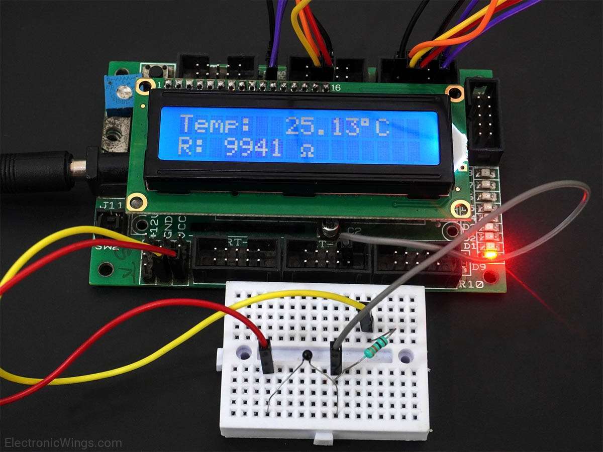
Thermocouple Interfacing with AVR ATmega16/ATmega32
A thermocouple is a device consisting of two dissimilar metals connected together creating a junction that is used for measuring the temperature.
Overview of Thermocouple
.jpg)
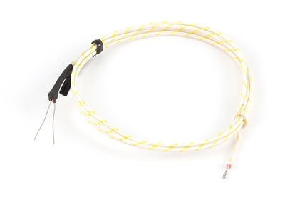
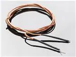
A thermocouple consists of two different conductors forming an electrical junction at different temperatures.
Due to thermo effect, thermocouples produce a voltage which is dependent on temperature.
Temperature can be found out from this voltage.
ADC output of this voltage can be processed by a microcontroller to give the temperature.
For more information about Thermocouple and how to use it, refer to the topic Thermocouple in the sensors and modules section.
For information about ADC in ATmega16 and how to use it, refer to the topic ADC in AVR ATmega16/ATmega32 in the ATmega inside section.
Connection Diagram of Thermocouple with ATmega16/32
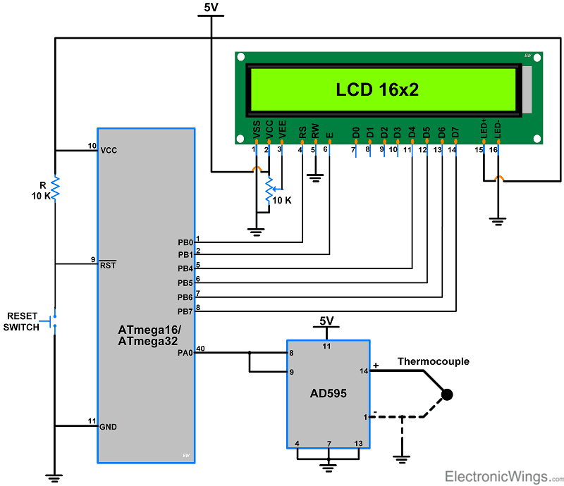
- The complete interfacing diagram of the thermocouple is shown in figure below.
AD595
- AD595 is a complete instrumentation amplifier (Monolithic Thermocouple Amplifiers) with a Cold Junction Compensation.
- AD595 is compatible with a K-type thermocouple, while AD594 is compatible with a J-type thermocouple.
- It combines ice point reference with the pre-calibrated amplifier to produce a high-level output (10mV/ºC) directly from the thermocouple output.
- AD595 gain trimmed to match transfer characteristic of K-type thermocouple at 25ºC. The output of a K-type thermocouple in this temperature range is 40.44uV/ºC.
- The resulting gain for AD595 is 247.3 (10mV/ºC divided by 40.44uV/ºC).
- The input offset voltage for AD595 is 11uV, this offset arises because the AD595 is trimmed for a 250 mV output while applying a 25°C thermocouple input.
- The output of AD595 is,
AD595 Output = (Type K Voltage + 11 uV) x 247.3
- The IC AD595 pin diagram is shown in the figure below.
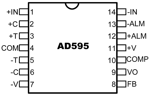
Note: if you connect +5 volt and ground to the AD595 you can measure the temperature 0ºC to +300ºC, for more information refers to AD595 datasheet.
Programming for Thermocouple
Steps:
- Initialize the ADC and LCD.
- Take the data from the AD595 instrumentation amplifier.
- Convert the ADC value into ºC using the below formula,
Why 0.0027 subtracted in the above formula
AD595 provides output as follows,
AD595 Output = (Type K Voltage + 11 uV) x 247.3
- The above formula shows AD595 provides output with amplified offset voltage. So, we have to eliminate the total offset voltage (11 uV * 247.3) to get an accurate temperature value.
Note: 11 uV is an offset voltage of the IC AD595 instrumentation amplifier for K-type thermocouple.
4. Display Temperature on 16x2 LCD.
Thermocouple Code for ATmega16/32
/*
 * ATmega16_Thermocouple.c
 *
 * http://www.electronicwings.com
 */


#define F_CPU 8000000UL
#include <avr/io.h>
#include "LCD16x2_4bit.h"
#include <util/delay.h>
#include <stdlib.h>

void ADC_Init()
{
	DDRA=0x0;		/* Make ADC port as input */
	ADCSRA = 0x87;		/* Enable ADC, fr/128  */
}

int ADC_Read()
{
	ADMUX = 0x40;		/* Vref: Avcc, ADC channel: 0 */
	ADCSRA |= (1<<ADSC);	/* Start conversion */
	while ((ADCSRA &(1<<ADIF))==0);	/*monitor end of conversion interrupt flag */
	ADCSRA |=(1<<ADIF);	/* Set the ADIF bit of ADCSRA register */
	return(ADCW);		/* Return the ADCW */
}

int main(void)
{
	lcdinit();		/* Initialize the 16x2 LCD */
	lcd_clear();		/* Clear the LCD */
	ADC_Init();		/* Initialize the ADC */
	char array[10];
	int ADC_value;
	float Temperature;
	lcd_gotoxy(0,0);	/* Set column and row */
	lcd_print("Temp: ");

    while(1)
	{
		ADC_value = ADC_Read();	/* store the analog data on a variable */

        /* convert analog voltage into ºC and subtract the offset voltage */

        Temperature = ((ADC_value * 4.88)-0.0027)/10.0;
		dtostrf(Temperature,3,2,array);
		lcd_gotoxy(6,0);	/* set column and row */
		lcd_print(array);	/* print array data on LCD */
		lcddata(0xDF);		/* ASCII value of '°' */
		lcd_print("C");
		_delay_ms(1000);	/* wait for 1 second */
	}
}
Video of Temperature Measurement using Atmega16/32
Components Used
Powered by
Downloads
Comments2
Join the discussion — share a question or tip.