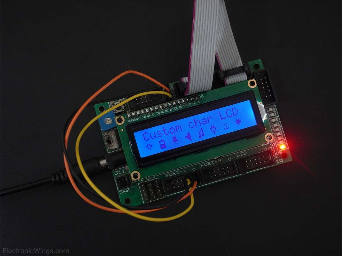
Interfacing LCD16x2 with AVR ATmega16/ATmega32 in 4-bit mode
LCD16x2 can be interfaced by using 4 data lines, which saves GPIO pins.
Overview of LCD16x2
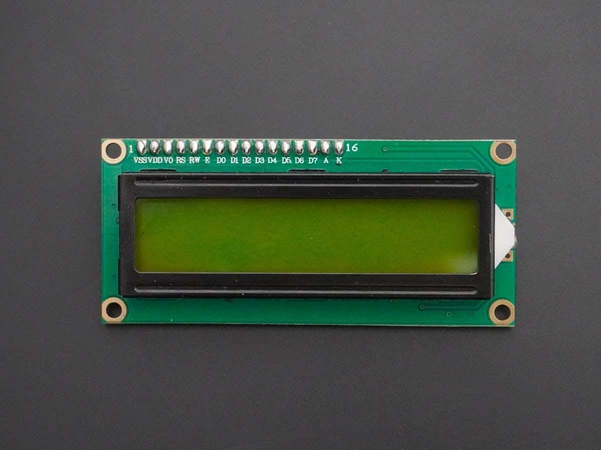
LCDs (Liquid Crystal Displays) are used for displaying status or parameters in embedded systems.
LCD 16x2 is a 16 pin device which has 8 data pins (D0-D7) and 3 control pins (RS, RW, EN). The remaining 5 pins are for supply and backlight for the LCD.
The control pins help us configure the LCD in command mode or data mode. They also help configure read mode or write mode and also when to read or write.
LCD 16x2 can be used in 4-bit mode or 8-bit mode depending on the requirement of the application. In order to use it, we need to send certain commands to the LCD in command mode and once the LCD is configured according to our need, we can send the required data in data mode.
For more information about LCD 16x2 and how to use it, refer to the topic LCD 16x2 display module in the sensors and modules section.
LCD16x2 Pinout

LCD16x2 4-bit Mode
- In 4-bit mode, data/command is sent in a 4-bit (nibble) format.
- To do this 1st send a Higher 4-bit and then send a lower 4-bit of data/command.
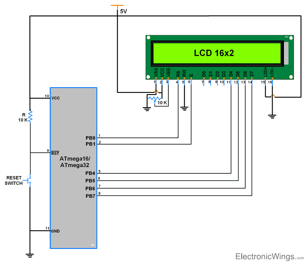
- Only 4 data (D4 - D7) pins of 16x2 of LCD are connected to the microcontroller and other control pins RS (Register select), RW (Read/write), E (Enable) is connected to other GPIO Pins of the controller.
Therefore, due to such connections, we can save four GPIO pins which can be used for another application.
Connection Diagram of LCD16x2 with ATmega16/32
Programming LCD16x2 4-bit mode with AVR ATmega16/Atmega32
Initialization
- Wait for 15ms, Power-on initialization time for LCD16x2.
- Send 0x02 command which initializes LCD 16x2 in 4-bit mode.
- Send 0x28 command which configures LCD in 2-line, 4-bit mode, and 5x8 dots.
- Send any Display ON command (0x0E, 0x0C)
- Send 0x06 command (increment cursor)
void LCD_Init (void)  /* LCD Initialize function */
{
	LCD_Dir = 0xFF;		/* Make LCD port direction as o/p */
	_delay_ms(20);		/* LCD Power ON delay always >15ms */

	LCD_Command(0x33);
	LCD_Command(0x32);	/* Send for 4 bit initialization of LCD  */
	LCD_Command(0x28);	/* 2 line, 5*7 matrix in 4-bit mode */
	LCD_Command(0x0c);	/* Display on cursor off */
	LCD_Command(0x06);	/* Increment cursor (shift cursor to right) */
	LCD_Command(0x01);	/* Clear display screen */
}
Now we successfully initialized LCD & it is ready to accept data in 4-bit mode to display.
To send command/data to 16x2 LCD we have to send higher nibble followed by lower nibble. As 16x2 LCD’s D4 - D7 pins are connected as data pins, we have to shift the lower nibble to the right by 4 before transmitting.
Command write function
- First, send a Higher nibble of command.
- Make RS pin low, RS=0 (command reg.)
- Make RW pin low, RW=0 (write operation) or connect it to ground.
- Give High to Low pulse at Enable (E).
- Send lower nibble of command.
- Give High to Low pulse at Enable (E).
void LCD_Command( unsigned char cmnd )
{
	LCD_Port = (LCD_Port & 0x0F) | (cmnd & 0xF0);/* Sending upper nibble */
	LCD_Port &= ~ (1<<RS);		/* RS=0, command reg. */
	LCD_Port |= (1<<EN);		/* Enable pulse */
	_delay_us(1);
	LCD_Port &= ~ (1<<EN);
	_delay_us(200);
	LCD_Port = (LCD_Port & 0x0F) | (cmnd << 4);/* Sending lower nibble */
	LCD_Port |= (1<<EN);
	_delay_us(1);
	LCD_Port &= ~ (1<<EN);
	_delay_ms(2);
}
Data write function
- First, send a Higher nibble of data.
- Make RS pin high, RS=1 (data reg.)
- Make RW pin low, RW=0 (write operation) or connect it to ground.
- Give High to Low pulse at Enable (E).
- Send lower nibble of data.
- Give High to Low pulse at Enable (E).
void LCD_Char( unsigned char data )
{
	LCD_Port = (LCD_Port & 0x0F) | (data & 0xF0);/* Sending upper nibble */
	LCD_Port |= (1<<RS);  /* RS=1, data reg. */
	LCD_Port|= (1<<EN);
	_delay_us(1);
	LCD_Port &= ~ (1<<EN);
	_delay_us(200);
	LCD_Port = (LCD_Port & 0x0F) | (data << 4);  /* Sending lower nibble */
	LCD_Port |= (1<<EN);
	_delay_us(1);
	LCD_Port &= ~ (1<<EN);
	_delay_ms(2);
}
LCD16x2 4 bit Mode Code for ATmega16/32
/*
   LCD16x2 4 bit ATmega16 interface
   http://www.electronicwings.com
*/

#define F_CPU 8000000UL			/* Define CPU Frequency e.g. here 8MHz */
#include <avr/io.h>			/* Include AVR std. library file */
#include <util/delay.h>			/* Include Delay header file */

#define LCD_Dir  DDRB			/* Define LCD data port direction */
#define LCD_Port PORTB			/* Define LCD data port */
#define RS PB0				/* Define Register Select pin */
#define EN PB1 				/* Define Enable signal pin */

void LCD_Command( unsigned char cmnd )
{
	LCD_Port = (LCD_Port & 0x0F) | (cmnd & 0xF0); /* sending upper nibble */
	LCD_Port &= ~ (1<<RS);		/* RS=0, command reg. */
	LCD_Port |= (1<<EN);		/* Enable pulse */
	_delay_us(1);
	LCD_Port &= ~ (1<<EN);

	_delay_us(200);

	LCD_Port = (LCD_Port & 0x0F) | (cmnd << 4);  /* sending lower nibble */
	LCD_Port |= (1<<EN);
	_delay_us(1);
	LCD_Port &= ~ (1<<EN);
	_delay_ms(2);
}

void LCD_Char( unsigned char data )
{
	LCD_Port = (LCD_Port & 0x0F) | (data & 0xF0); /* sending upper nibble */
	LCD_Port |= (1<<RS);		/* RS=1, data reg. */
	LCD_Port|= (1<<EN);
	_delay_us(1);
	LCD_Port &= ~ (1<<EN);

	_delay_us(200);

	LCD_Port = (LCD_Port & 0x0F) | (data << 4); /* sending lower nibble */
	LCD_Port |= (1<<EN);
	_delay_us(1);
	LCD_Port &= ~ (1<<EN);
	_delay_ms(2);
}

void LCD_Init (void)			/* LCD Initialize function */
{
	LCD_Dir = 0xFF;			/* Make LCD port direction as o/p */
	_delay_ms(20);			/* LCD Power ON delay always >15ms */

	LCD_Command(0x02);		/* send for 4 bit initialization of LCD  */
	LCD_Command(0x28);              /* 2 line, 5*7 matrix in 4-bit mode */
	LCD_Command(0x0c);              /* Display on cursor off*/
	LCD_Command(0x06);              /* Increment cursor (shift cursor to right)*/
	LCD_Command(0x01);              /* Clear display screen*/
	_delay_ms(2);
}

void LCD_String (char *str)		/* Send string to LCD function */
{
	int i;
	for(i=0;str[i]!=0;i++)		/* Send each char of string till the NULL */
	{
		LCD_Char (str[i]);
	}
}

void LCD_String_xy (char row, char pos, char *str)	/* Send string to LCD with xy position */
{
	if (row == 0 && pos<16)
	LCD_Command((pos & 0x0F)|0x80);	/* Command of first row and required position<16 */
	else if (row == 1 && pos<16)
	LCD_Command((pos & 0x0F)|0xC0);	/* Command of first row and required position<16 */
	LCD_String(str);		/* Call LCD string function */
}

void LCD_Clear()
{
	LCD_Command (0x01);		/* Clear display */
	_delay_ms(2);
	LCD_Command (0x80);		/* Cursor at home position */
}

int main()
{
	LCD_Init();			/* Initialization of LCD*/

	LCD_String("ElectronicWINGS");	/* Write string on 1st line of LCD*/
	LCD_Command(0xC0);		/* Go to 2nd line*/
	LCD_String("Hello World");	/* Write string on 2nd line*/
	while(1);
}
Components Used
Powered by
Downloads
Comments18
Join the discussion — share a question or tip.
- MO
Hi how define D4 to D7 PIN from PORTB ?
- AL
Hi. I connected 20x4 LCD instead of 16x4. And apply the source code from this article, but I can’t figure out how to connect the third and fourth lines. What part I need to change or maybe add some where in this code to make it possible to work with the third and fourth line?
- ENenthusiasticgeek· edited
Hi What is the license of your source code? I have modified your source code to work on ATMEGA2560 . I have added floating point and int display functions that I designed. I have given you credit to your URL but I couldn't find license . All my source code is released under MIT license on this repo. https://github.com/enthusiasticgeek/Elegoo_Mega_2560/blob/master/LCD16x2_4bit.c If you have license I will gladly add it. Thanks.
- DA
Replying to @KavanDave
It's most probably due to your Vcc not meeting the LCD controller's requirement. It must reach 4.5v in 10ms for 5v operation, or 2.7v in 10ms for 3v operation (see Hitachi HD44780U datasheet page 59). If this condition is not met, the internal reset circuit will not work, and you'll need to perform a manual init by sending 4 init nibbles at specific intervals (datasheet page 46): Power on -> wait at least 15ms -> send 0x3 -> wait at least 4.1ms -> send 0x3 -> wait at least 100us -> send 0x3 -> send 0x2 -> follow by the rest of the initialization. Since Vcc rise time varies across hardware and is hard to guarantee, it is best to perform the manual init anyway.
- DA
Replying to @davidwongcy
The modified code is as follow: void LCD_nibble_cmd(unsigned char nibble) { LCD_Port = (LCD_Port & 0x0F) | (nibble << 4); /* send nibble */ LCD_Port &= ~ (1<<RS); /* RS=0, command reg. */ LCD_Port|= (1<<EN); _delay_us(1); LCD_Port &= ~ (1<<EN); } void LCD_Init (void) /* LCD Initialize function */ { LCD_Dir = 0xFF; /* Make LCD port direction as o/p */ _delay_ms(20); /* LCD Power ON delay min 15ms */ LCD_nibble_cmd(3); /* manual 4 bit initialization of LCD */ _delay_ms(5); /* min 4.1ms */ LCD_nibble_cmd(3); _delay_ms(1); /* min 100us */ LCD_nibble_cmd(3); LCD_nibble_cmd(2); /* this is no longer needed LCD_Command(0x02); /* send for 4 bit initialization of LCD */ */ LCD_Command(0x28); /* 2 line, 5*7 matrix in 4-bit mode */ LCD_Command(0x0c); /* Display on cursor off*/ LCD_Command(0x06); /* Increment cursor (shift cursor to right)*/ LCD_Command(0x01); /* Clear display screen*/ _delay_ms(2); }
Related Guides
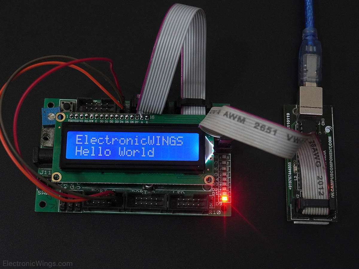
LCD16x2 Interfacing with AVR ATmega16/ATmega32
Read guide