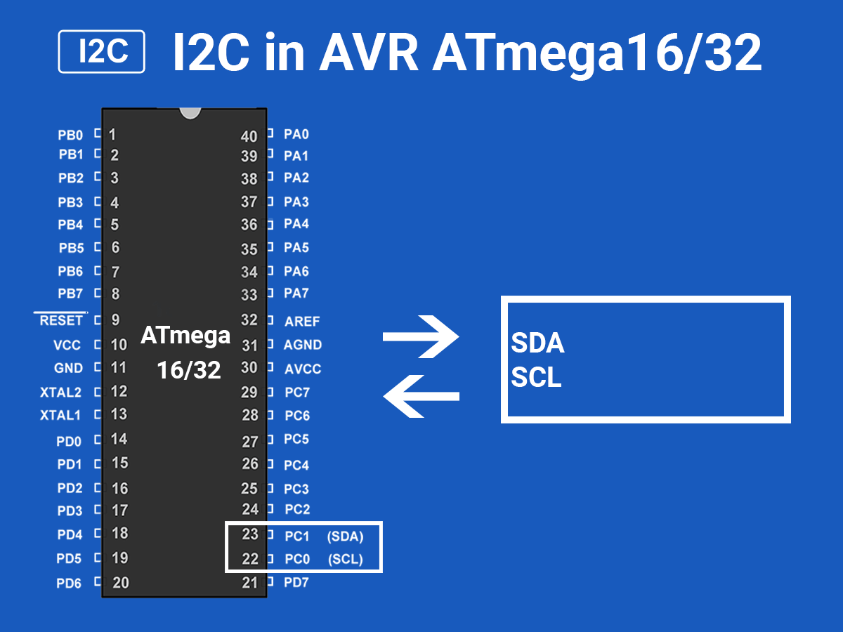
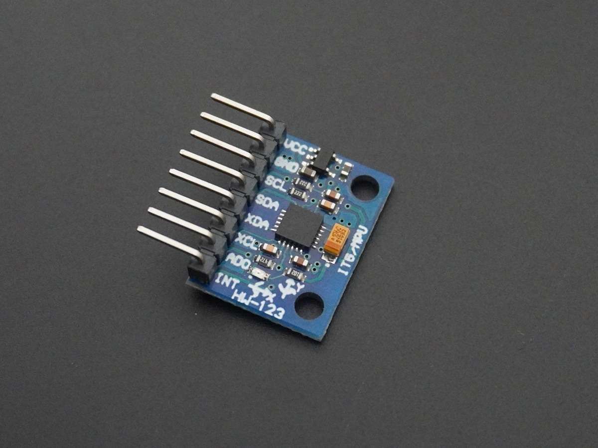
MPU6050 (Gyroscope + Accelerometer + Temperature) interface with AVR ATmega16.
MPU6050 (Gyroscope + Accelerometer + Temperature) is a combination of 3-axis Gyroscope, 3-axis Accelerometer and Temperature sensor with onboard Digital Motion Processor (DMP). It is used in mobile devices, motion enabled games, 3D mice, Gesture (motion command) technology, etc.
Overview of Gyroscope
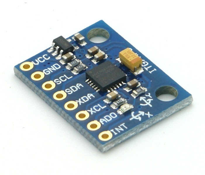
The MPU6050 sensor module is an integrated 6-axis Motion tracking device.
- It has a 3-axis Gyroscope, 3-axis Accelerometer, Digital Motion Processor, and a Temperature sensor, all in a single IC.
- It can accept inputs from other sensors like a 3-axis magnetometer, and pressure sensor using its Auxiliary I2C bus.
- If an external 3-axis magnetometer is connected, it can provide complete 9-axis Motion Fusion output.
- A microcontroller can communicate with this module using the I2C communication protocol.
- Gyroscope and accelerometer reading along X, Y, and Z axes are available in 2’s complement form. The temperature reading is available in a signed integer form.
- Gyroscope readings are in degrees per second (DPS) unit; Accelerometer readings are in g unit, and Temperature reading is in degrees Celsius.
For more information about the MPU6050 Sensor Module and how to use it, refer to the topic MPU6050 Sensor Module in the sensors and modules section.
Connection Diagram of MPU6050 with ATmega16/32
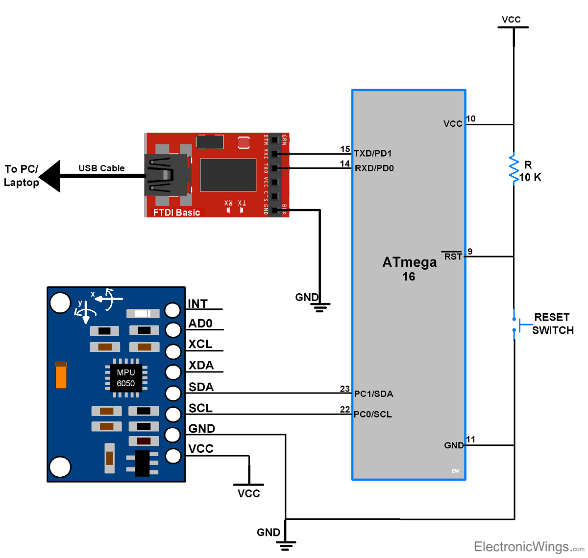
The interfacing of the MPU-6050 module with ATmega16 is shown in the below figure.
MPU6050 Example Using ATmega16/32
Let's program MPU6050 (Gyro meter + Accelerometer + Temperature) sensor module with AVR-based ATmega16 to read all sensor values and send all values on computer terminals over USART.
- MPU-6050 has an I2C communication interface to connect it with the I2C of ATmega16.
- The module requires a +5V DC power supply, so connect it to the VCC pin of the module.
- Connect the ground to the GND pin of the module.
- Here we have used FTDI serial to USB converter to send values serially to a computer terminal.
MPU6050 Gyroscope Code for ATmega16/32
/*
 * ATmega16 Interface with MPU6050
 * http://www.electronicwings.com
 *
 */


#define F_CPU 8000000UL		/* Define CPU clock Frequency 8MHz */
#include <avr/io.h>			/* Include AVR std. library file */
#include <util/delay.h>		/* Include delay header file */
#include <inttypes.h>		/* Include integer type header file */
#include <stdlib.h>			/* Include standard library file */
#include <stdio.h>			/* Include standard I/O library file */
#include "MPU6050_res_define.h"	/* Include MPU6050 register define file */
#include "I2C_Master_H_file.h"	/* Include I2C Master header file */
#include "USART_RS232_H_file.h"	/* Include USART header file */

float Acc_x,Acc_y,Acc_z,Temperature,Gyro_x,Gyro_y,Gyro_z;

void Gyro_Init()			/* Gyro initialization function */
{
	_delay_ms(150);			/* Power up time >100ms */
	I2C_Start_Wait(0xD0);	/* Start with device write address */
	I2C_Write(SMPLRT_DIV);	/* Write to sample rate register */
	I2C_Write(0x07);		/* 1KHz sample rate */
	I2C_Stop();

	I2C_Start_Wait(0xD0);
	I2C_Write(PWR_MGMT_1);	/* Write to power management register */
	I2C_Write(0x01);		/* X axis gyroscope reference frequency */
	I2C_Stop();

	I2C_Start_Wait(0xD0);
	I2C_Write(CONFIG);		/* Write to Configuration register */
	I2C_Write(0x00);		/* Fs = 8KHz */
	I2C_Stop();

	I2C_Start_Wait(0xD0);
	I2C_Write(GYRO_CONFIG);	/* Write to Gyro configuration register */
	I2C_Write(0x18);		/* Full scale range +/- 2000 degree/C */
	I2C_Stop();

	I2C_Start_Wait(0xD0);
	I2C_Write(INT_ENABLE);	/* Write to interrupt enable register */
	I2C_Write(0x01);
	I2C_Stop();
}

void MPU_Start_Loc()
{
	I2C_Start_Wait(0xD0);		/* I2C start with device write address */
	I2C_Write(ACCEL_XOUT_H);	/* Write start location address from where to read */
	I2C_Repeated_Start(0xD1);	/* I2C start with device read address */
}

void Read_RawValue()
{
	MPU_Start_Loc();			/* Read Gyro values */
	Acc_x = (((int)I2C_Read_Ack()<<8) | (int)I2C_Read_Ack());
	Acc_y = (((int)I2C_Read_Ack()<<8) | (int)I2C_Read_Ack());
	Acc_z = (((int)I2C_Read_Ack()<<8) | (int)I2C_Read_Ack());
	Temperature = (((int)I2C_Read_Ack()<<8) | (int)I2C_Read_Ack());
	Gyro_x = (((int)I2C_Read_Ack()<<8) | (int)I2C_Read_Ack());
	Gyro_y = (((int)I2C_Read_Ack()<<8) | (int)I2C_Read_Ack());
	Gyro_z = (((int)I2C_Read_Ack()<<8) | (int)I2C_Read_Nack());
	I2C_Stop();
}

int main()
{
	char buffer[20], float_[10];
	float Xa,Ya,Za,t;
	float Xg=0,Yg=0,Zg=0;
	I2C_Init();			/* Initialize I2C */
	Gyro_Init();		/* Initialize Gyro */
	USART_Init(9600);	/* Initialize USART with 9600 baud rate */

	while(1)
	{
		Read_RawValue();

		/* Divide raw value by sensitivity scale factor */
		Xa = Acc_x/16384.0;
		Ya = Acc_y/16384.0;
		Za = Acc_z/16384.0;

		Xg = Gyro_x/16.4;
		Yg = Gyro_y/16.4;
		Zg = Gyro_z/16.4;

		/* Convert temperature in /c using formula */
		t = (Temperature/340.00)+36.53;

		/* Take values in buffer to send all parameters over USART */
		dtostrf( Xa, 3, 2, float_ );
		sprintf(buffer," Ax = %s g\t",float_);
		USART_SendString(buffer);

		dtostrf( Ya, 3, 2, float_ );
		sprintf(buffer," Ay = %s g\t",float_);
		USART_SendString(buffer);

		dtostrf( Za, 3, 2, float_ );
		sprintf(buffer," Az = %s g\t",float_);
		USART_SendString(buffer);

		dtostrf( t, 3, 2, float_ );
		/* 0xF8 Ascii value of degree on serial */
		sprintf(buffer," T = %s%cC\t",float_,0xF8);
		USART_SendString(buffer);

		dtostrf( Xg, 3, 2, float_ );
		sprintf(buffer," Gx = %s%c/s\t",float_,0xF8);
		USART_SendString(buffer);

		dtostrf( Yg, 3, 2, float_ );
		sprintf(buffer," Gy = %s%c/s\t",float_,0xF8);
		USART_SendString(buffer);

		dtostrf( Zg, 3, 2, float_ );
		sprintf(buffer," Gz = %s%c/s\r\n",float_,0xF8);
		USART_SendString(buffer);
	}
}
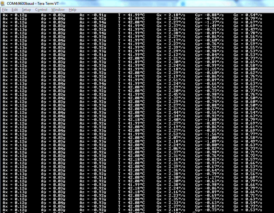
MPU6050 Output Window of Terminal
The output window will show all values mentioned below
Ax = Accelerometer x-axis data in g unit
Ay = Accelerometer y-axis data in g unit
Az = Accelerometer z-axis data in g unit
T = temperature in degree/Celcius
Gx = Gyro x axis data in degree/seconds unit
Gy = Gyro y axis data in degree/seconds unit
Gz = Gyro z axis data in degree/seconds unit
Components Used
Powered by
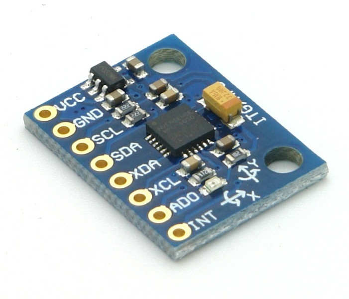
MPU6050 (Gyroscope + Accelerometer + Temperature) is a combination of 3-axis Gyroscope, 3-axis Accelerometer and Temperature sensor with on-chip Digital Motion Processor (DMP). It is used in mobile devices, motion enabled games, 3D mice, Gesture (motion command) technology etc
410-MPU-6050
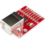
CP2103 is single chip USB to UART Bridge. It supports USB 2.0 protocol.
634-CP2103-GMR
Downloads
Comments22
Join the discussion — share a question or tip.
- MO
Hi how can i use this code in codevision? please guide me
- NO
Hi sir. May i know how i can change the coding for Atmega328 because i faced error with the MPU6050 res.h and recipe for target main.o failed when i try to copy the coding to another file
- ZE
How would you do if you want to use this code with atmega328p chip instead?
- JOJohnSanchez· edited
Hello, thanks for the code so much . I just want to ask how can I get the data for my PC exactly as a HID gyroscope , not as a console text ?
- DA
Hello, I have problems with the code you have provided, I am using an Atmega32A and change the frequencies in all the libraries, but in TeraTerm it gives me negative zeros in the 6 axes, also in the Proteus simulator. Excuse my English grief, greetings from Ecuador.
- AN
why do we need to use USART communication in this?whats buffer here?
- AN
Replying to @lokeshc
When i opened a new connection iam not able to select the serial communication radio button, its greyed out! Do you know what to do here?
- AN
Replying to @lokeshc
Tera term works fine now, i selected atmega328p as the board in the project,now its showing errors such as UCSRB undeclared and so on.What has to be done?
- RA
Hi, Thank you very much for your source code and hardware information. It is really great work. i have connected mpu6050 to ATMEGA32A micorcontroller and i succeeded to get raw data from 3 axis accelerometer/Gyroscopes from MPU6050. i want to find ROll, Pitch and YAW angles. how can i find or calculate from these raw data from mpu6050? any help will be appreciated
- LO
@Rascal: Hello friend, make sure that your MPU6050 is connected to atmega16 properly. since the i2c functions used in above example using while(1) methods for sending and receiving the data. so the situation may come while your connection gets loose and i2c functions will get stuck to while(1) behaviour due to no response from slave device(MPU6050 here). Also you need to change the f_cpu in every library used for above example i.e. you need to change the f_cpu in i2c library and uart library as well. you are using external crystal so i hope you already sets controller to use external crystal. try above things and let me know if still it getting stucks