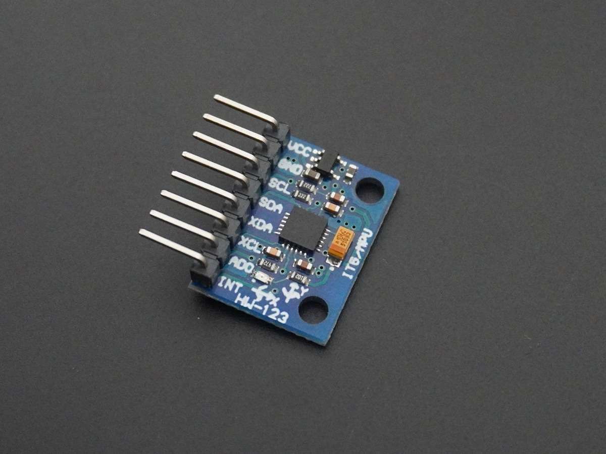
MPU6050 (Gyroscope + Accelerometer + Temperature) interface with PIC18F4550.
MPU6050 (Gyroscope + Accelerometer + Temperature) is a combination of a 3-axis Gyroscope, 3-axis Accelerometer, and Temperature sensor with an onboard Digital Motion Processor (DMP). It is used in mobile devices, motion enabled games, 3D mice, Gesture (motion command) technology, etc.
Introduction
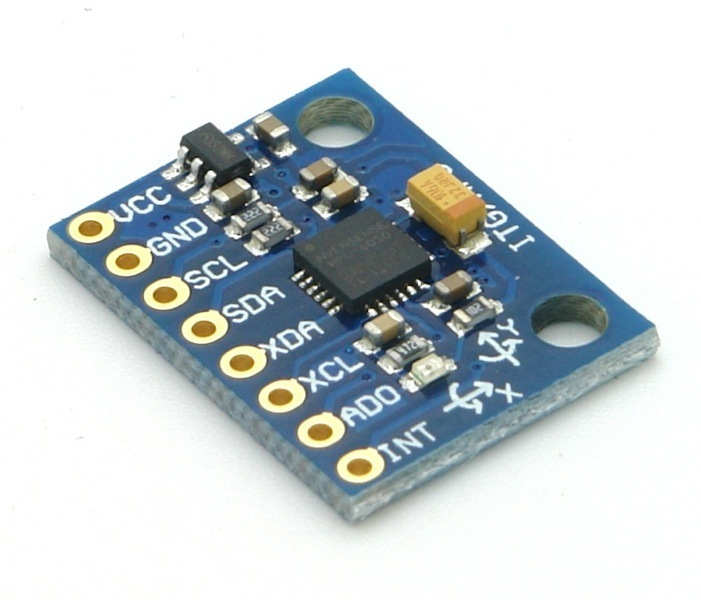
The MPU6050 sensor module is an integrated 6-axis Motion tracking device.
- It has a 3-axis Gyroscope, 3-axis Accelerometer, Digital Motion Processor, and a Temperature sensor, all in a single IC.
- It can accept inputs from other sensors like a 3-axis magnetometer, a pressure sensor using its Auxiliary I2C bus.
- If the external 3-axis magnetometer is connected, it can provide complete 9-axis Motion Fusion output.
- A microcontroller can communicate with this module using the I2C communication protocol.
- Gyroscope and accelerometer reading along X, Y, and Z axes are available in 2’s complement form. The temperature reading is available in a signed integer form.
- Gyroscope readings are in the degrees per second (DPS) unit; Accelerometer readings are in g unit, and Temperature reading is in degrees Celsius.
For more information about the MPU6050 Sensor Module and how to use it, refer to the topic MPU6050 Sensor Module in the sensors and modules section.
Programming PIC18F4550 for MPU6050
Let's Interface and program PIC18F4550 with MPU6050 (Gyro meter + Accelerometer + Temperature) sensor module to read all sensor values and send all values on computer terminals over USART.
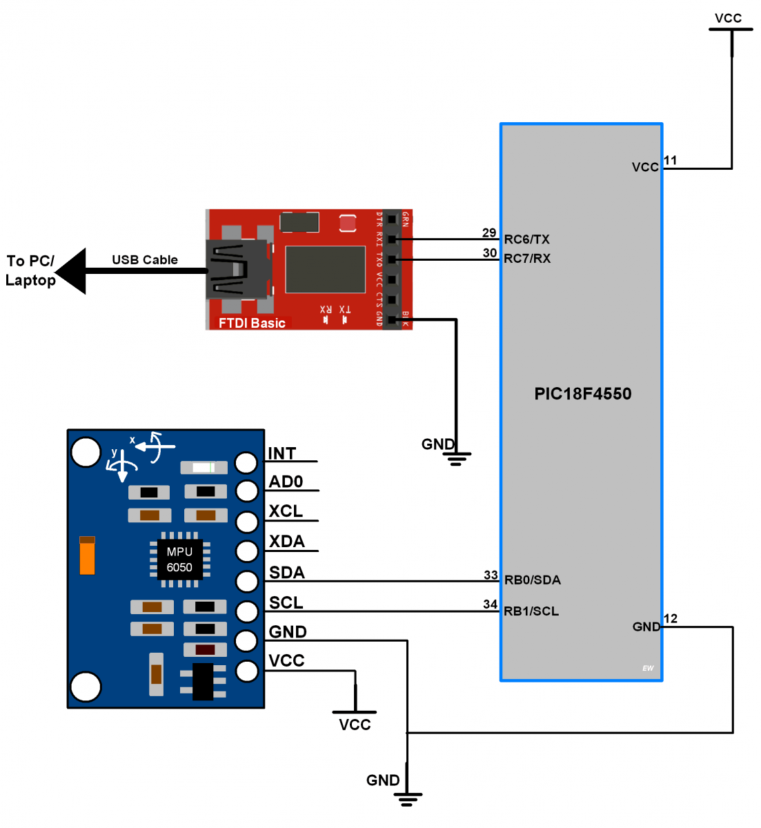
- As MPU-6050 has an I2C communication interface, we are connecting it with I2C of PIC18F4550.
- The module requires a +5V DC power supply, so connect it to the VCC pin of a module.
- Connect ground to the GND pin of a module.
- Here we have used FTDI serial to USB converter to send values serially to the computer terminal.
Connection Diagram of MPU6050 to PIC18F4550
MPU6050 Code for PIC18F4550
/*
 * PIC18F4550 Interface with MPU-6050
 * http://www.electronicwings.com
 */

#include <pic18f4550.h>
#include <stdio.h>
#include <stdlib.h>
#include "USART_Header_File.h"
#include "I2C_Master_File.h"
#include "MPU6050_res_define.h"
#include "Configuration_header_file.h"

void MPU6050_Init()		/* Gyro initialization function */
{
	MSdelay(150);		/* Power up time >100ms */
	I2C_Start_Wait(0xD0);	/* Start with device write address */
	I2C_Write(SMPLRT_DIV);	/* Write to sample rate register */
	I2C_Write(0x07);	/* 1KHz sample rate */
	I2C_Stop();

	I2C_Start_Wait(0xD0);
	I2C_Write(PWR_MGMT_1);	/* Write to power management register */
	I2C_Write(0x01);	/* X axis gyroscope reference frequency */
	I2C_Stop();

	I2C_Start_Wait(0xD0);
	I2C_Write(CONFIG);	/* Write to Configuration register */
	I2C_Write(0x00);	/* Fs = 8KHz */
	I2C_Stop();

	I2C_Start_Wait(0xD0);
	I2C_Write(GYRO_CONFIG);	/* Write to Gyro configuration register */
	I2C_Write(0x18);	/* Full scale range +/- 2000 degree/C */
	I2C_Stop();

	I2C_Start_Wait(0xD0);
	I2C_Write(INT_ENABLE);	/* Write to interrupt enable register */
	I2C_Write(0x01);
	I2C_Stop();
}

void MPU_Start_Loc()
{
	I2C_Start_Wait(0xD0);	/* I2C start with device write address */
	I2C_Write(ACCEL_XOUT_H);/* Write start location address to read */
	I2C_Repeated_Start(0xD1);/* I2C start with device read address */
}

void main()
{
	char buffer[20];
	int Ax,Ay,Az,T,Gx,Gy,Gz;
	float Xa,Ya,Za,t,Xg,Yg,Zg;
    	OSCCON = 0x72;
    	I2C_Init();		/* Initialize I2C */
	MPU6050_Init();		/* Initialize Gyro */
	USART_Init(9600);	/* Initialize USART with 9600 baud rate */

	while(1)
	{
		MPU_Start_Loc();
		/* Read Gyro values continuously & send to terminal over UART */
		Ax = (((int)I2C_Read(0)<<8) | (int)I2C_Read(0));
		Ay = (((int)I2C_Read(0)<<8) | (int)I2C_Read(0));
		Az = (((int)I2C_Read(0)<<8) | (int)I2C_Read(0));
		T =  (((int)I2C_Read(0)<<8) | (int)I2C_Read(0));
		Gx = (((int)I2C_Read(0)<<8) | (int)I2C_Read(0));
		Gy = (((int)I2C_Read(0)<<8) | (int)I2C_Read(0));
		Gz = (((int)I2C_Read(0)<<8) | (int)I2C_Read(1));
		I2C_Stop();


		/* Divide raw value by sensitivity scale factor */
		Xa = (float)Ax/16384.0;
		Ya = (float)Ay/16384.0;
		Za = (float)Az/16384.0;
		Xg = (float)Gx/131.0;
		Yg = (float)Gy/131.0;
		Zg = (float)Gz/131.0;
		t = ((float)T/340.00)+36.53;/* Convert temperature in °/c */


		/* Take values in buffer to send all parameters over USART */
		sprintf(buffer," Ax = %.2f g\t",Xa);
		USART_SendString(buffer);

		sprintf(buffer," Ay = %.2f g\t",Ya);
		USART_SendString(buffer);

		sprintf(buffer," Az = %.2f g\t",Za);
		USART_SendString(buffer);

		/* 0xF8 Ascii value of degree '°' on serial */
		sprintf(buffer," T = %.2f%cC\t",t,0xF8);
		USART_SendString(buffer);

		sprintf(buffer," Gx = %.2f%c/s\t",Xg,0xF8);
		USART_SendString(buffer);

		sprintf(buffer," Gy = %.2f%c/s\t",Yg,0xF8);
		USART_SendString(buffer);

		sprintf(buffer," Gz = %.2f%c/s\r\n",Zg,0xF8);
		USART_SendString(buffer);
	}
}
Output Window of Terminal
Output window will show all values mentioned below
Ax = Accelerometer x axis data in g unit
Ay = Accelerometer y axis data in g unit
Az = Accelerometer z axis data in g unit
T = temperature in degree/celcius
Gx = Gyro x axis data in degree/seconds unit
Gy = Gyro y axis data in degree/seconds unit
Gz = Gyro z axis data in degree/seconds unit
.png)
Components Used
Powered by
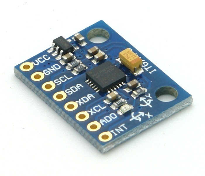
MPU6050 (Gyroscope + Accelerometer + Temperature) is a combination of 3-axis Gyroscope, 3-axis Accelerometer and Temperature sensor with on-chip Digital Motion Processor (DMP). It is used in mobile devices, motion enabled games, 3D mice, Gesture (motion command) technology etc
410-MPU-6050
Downloads
Comments35
Join the discussion — share a question or tip.
- MO
Hello. Thank you so much Ali. Good luck.
- VA
How to make it work with pic16f877a instead of PIC18F4550?
- DR
Hi In the schematic diagram i think there is a mistake the pin RC6 and RC7 in this MCU are the pins 25 and 26 respectively.
- OS
thank you very much for this tutorial sir, but sir I want to ask, how do you know which of the sensors register to write to be able to initialize the sensor, because it's very confusing, like how did you know you have to write to the sample rate register, looking forward to your reply sir
- AL
I have a question, why do you use only "Gyro initialization function"? Where is "Accel initialization function?
- LO
The 7-bit address of MPU6050 is 0x68 but for I2C write/read we need to send 7-bit address along with read and write bit. So, its address become 0xD0 for write and 0xD1 for read. The address of MPU9250 will be same. 7-bit address + (read/write bit). I didn't know their 7-bit addresses. But you can calculate it as above.
- IS
Hi I have a really basic question on this example. First of all it works perfectly. However my aim was to try and change the project to use MPU9250. When I plugged in an MPU9250 to my amazement it also worked without changes. I then tried to get the MPU9250 to give me magnetometer values(without success). In the MPU6050 project you use 0xD0 as the MPU6050 device address. I expected to need 0x68 for this address but this does not work. I seem to be missing something really basic here and I have compared it to other Arduino MPU9250 (and MPU6050) projects and cannot see any evidence that 0xD0 is the MPU9250_ADDRESS. I compared it to your Arduino project for MPU6050 interface and the MPU9250_ADDRESS is 0x68 (ADO=0). So what is the 0xD0 address? and how does it work in your project?
- RI
Hi, Which motion app can i use to see MPU6050 motion on screen.I can find info on arduino ut not for pic.please guide Thank u in advance.
- AU
@RISHI SHARMA: hey rishi..!! refer https://github.com/jrowberg/i2cdevlib/tree/master/Arduino/MPU6050 example in arduino to see the mpu6050 motion on screen which uses internal dmp processing. same you need to do in pic..!! using internal dmp we can get directly motion values. these motion values later used to display motion on screen. Hope you will do it..!!
- RI
Replying to @authorized
@authorized pirates: Hey,I sincerely appreciate your answers!!!! I am new in this field and i require a lot of learning!!! I have following questions 1. What exactly is motion apps?HOw to get it? 2. I have seen people moving some structures on their screen on basis of output from gyro using arduino!! What exactly they are doing? is there any such interface for pic too? 3.What additional things I require to interface mpu6050 with pc?I only have a pickit3 pic and mpu.
- AU
Replying to @rishisharma4397
@RISHI SHARMA: motion apps is just about to find out physical motion of object with respect to their axes. invensense has developed motion apps demo code which is implemented in above mentioned arduino application of mpu6050. internal digital motion processing(DMP) unit in mpu6050 is used to calculate motion values from accelero and gyro readings. motion values contains axes readings as well as quaternion values (w, x, y, z). using these quaternion number system we can calculate objects movement around axes. to enable dmp features in mpu6050 we required to configure it first, in which we need to write its configure registers. after configuration we can read motion values from dmp through fifo or directly. this motion data/quternion data which consist of mpu6050 oreintation information is transferred to visual processing applications on pc or enabled devices. mostly demos are available on internet are created by processing (Processing is an open source computer programming language and integrated development environment) sketches or using matlab. using such visual development environment we can create visual moving structures by mpu6050 motion data. this is just brief case. you need to understand the basic mathematics required to calculate these axes angles and their rotation as well as about quaternions. once you understand how mpu6050 calculates these motion data. then its easy for you to plot its 3d structure using processing or matlab. its possible with pic, but you need to do many trials to reach its motion data. hope you will do it...!! gn
- RI
Replying to @authorized
@authorized pirates: Thanks a lot !!!! I will search what you mentioned It willl help me a lot!! If possible ,please do share any links or data that you have regarding interfacing pic with mpu6050!!! Thanks a lot!!!!
- AUauthorized· edited
Replying to @rishisharma4397
@RISHI SHARMA: I don't know any link for it....just googled it. . . above example is good for understanding the basic values from accelero and gyro. for more interesting results and applications we need to play with maths (mostly with quaternions). .. well... hope you will share if you succeed in doing with pic...best luck ..!!
- RI
Hey! I want precise values from gyro for my application In this code we get a lot of values continuously Is it possible to get precise value by using kalman filter or by some other means? If yes then how? By precise I mean Eg. If I tilt a plate by 0.5 or 1 degree(say along x axis) can I get that valueexactly from gyro? Experts do reply!! Thank you in advance :)
- LO
@RISHI SHARMA: Hello rishi, yes it is possible..!! you need to check the datasheet of mpu6050 where there are parameters available as "Sensitivity Scale Factor", "Full scale range" to select the range of sensitivity. By selecting the lowest range and bigger scale factor you can get minimum possible variations from mpu6050 for accelero as well as gyro readings. To measure tilt accelero is used whereas gyro gives us speed of rotation around the axis. it depends on the application that decides to use or not filter option for mpu6050. we can use filter option as well to refine the variations. also we can use map functions to minimize its min-max range. there are many ways by which we can minimize the variations and get better fine precise results.
- RI
Replying to @lokeshc
@Lokesh Chandak: Thank you so much!!! In your anwer you have mentioned "it depends on the application that decides to use or not filter option for mpu6050. we can use filter option as well to refine the variations. also we can use map functions to minimize its min-max range." 1.Is there any inbuilt filter that we can use or we have to add values using other method? 2.How can I set a reference for gyro and how can I ensure that it returns to zero when it reaches reference location. Various information is available about arduino but I am not able to find anything on reference setting in pic.It would be nice if you could help me out. Thank you in advance.
- RI
Replying to @lokeshc
@Lokesh Chandak: Thank you so much!!! In your anwer you have mentioned "it depends on the application that decides to use or not filter option for mpu6050. we can use filter option as well to refine the variations. also we can use map functions to minimize its min-max range." 1.Is there any inbuilt filter that we can use or we have to add values using other method? 2.How can I set a reference for gyro and how can I ensure that it returns to zero when it reaches reference location. Various information is available about arduino but I am not able to find anything on reference setting in pic.It would be nice if you could help me out. Thank you in advance.
- RI
Hey! I want precise values from gyro for my application In this code we get a lot of values continuously Is it possible to get precise value by using kalman filter or by some other means? If yes then how? By precise I mean Eg. If I tilt a plate by 0.5 or 1 degree(say along x axis) can I get that valueexactly from gyro? Experts do reply!! Thank you in advance :)
- RIrishisharma4397· edited
Hey, i wrote my own code referring yours and it was working absolutely fine.However for our application we had to switch from pickit3 to our self made board.Our board is operational for other codes so that is not the issue. We are using HID Bootloader and running the same code.There is no output on hc05 terminal.Whenever we put sprintf function it doesnt show anything.we tries using only uart and its working well. on doing further analysis we found there is some issue with bf bit because after while loop of checking bf its not coming out please help thank you in advance
- LO
@RISHI SHARMA: hello rishi, nice to hear it works for you..!! in a case, "We are using HID Bootloader and running the same code.There is no output on hc05 terminal.Whenever we put sprintf function it doesnt show anything.we tries using only uart and its working well." it sounds like you are commented sprintf lines and its working..... and in case, "on doing further analysis we found there is some issue with bf bit because after while loop of checking bf its not coming out" if you are sure about bf bit issue then try with sspif interrupt flag monitor before checking for received character. it confusing me as you said it is working before and since your changing the board its not. in my opinion I will say if it working at least once then it should work on any board with same controller. for sprintf if you have changed buffer size to minimum than it required then it will make issue of buffer leaks, so make sure your buffer size is at least greater than it required. if you still facing same issue share your code snip for my better understand
- RI
Replying to @lokeshc
@Lokesh Chandak: Thanks for reply. I tried what you mentioned and now I came to the conclusion that the issue is of Sprintf.I am able to send data using: void USART_send(char data) { while(PIR1bits.TXIF==0); //wait till txreg is free TXREG=data; } However when I write Sprintf in main function nothing is printed on HC05 terminal. It was working for pickit3 but not for my board. Can it be a problem of HID (usb) bootloader? Or can it be due to Sprintf? If yes, is there any alternative for sending 16 bit data on bt terminal
- AU
Replying to @rishisharma4397
@RISHI SHARMA: Hey, if USART is working then it clearly indicates that your board is fine, if your board is working with all other codes e.g. led blink then there is no issue with your board. you need to debug every line of your code to find out the issue, it seems like sprintf function in above program is used to make string format of values and copy it in the local buffer. and then send this char buffer over serial usart. in above process sprintf just used to copy data to buffer in string format. bootloader is just peace of code found at end of program space which is used to write your hex code to program space. there is no issue with bootloader if it uploading and working fine with your other sample codes. if you want alternative for sending data and your USART function is working then you can use integer/float to string/char conversion technique and then send them over USART. hope it will work...!!
- RI
Replying to @authorized
@authorized pirates: Thank you soo much for reply. It worked by changing buffer size
- AU
@Vijetha Kanchan: If you see MPU6050 Accel and gyro registers addresses, you will notice that ACCEL_XOUT_H register is at the start of all accel & gyro registers. hence we can start to read all registers data from ACEL_XOUT_H registers. now from ACCEL_XOUT_H register, we can read all other registers. when ACCEL_XOUT_H register reading gets completes controller sends an acknowledgment to MPU6050 and hence its address gets auto increment to next register address and we can read next register without addressing it. mpu_start_loc() function used to set start address location i.e. to ACCEL_XOUT_H. after all registers reading done with acknowledgment except the last register for which controller does not acknowledge and MPU6050 consider it as a not acknowledgment.