PIC18F4550 External Interrupt
The external interrupt is a mechanism for devices that interrupts the controller to get the attention of the controller. Here we are going to toggle LED using a switch as an external interrupt.
Introduction
Interrupts are the signals which alter the flow of an executing program by causing the microcontroller jumps to the Interrupt Service Routine to serve to interrupt. These interrupts are given to the microcontroller unit through the external pins of the microcontroller.
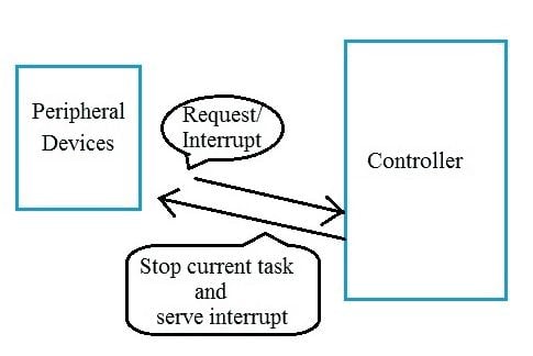
- Once the controller completes the routine, it returns to the location from where it had made a jump.
- In cases where interrupts are not used, the program would need to constantly poll the input signals to monitor external events for catching the pulses when they occurred. But in some cases, the program can miss an event.
- E.g. An infrared slot sensor trying to catch a coin drop. In this situation, using an interrupt can free the microcontroller to get some other work done while not missing the input. In such cases, external interrupts are used.
External Interrupt Pins
PIC18F4550 has three external hardware interrupts - INT0, INT1, and INT2. They are on PORTB pins RB0, RB1, and RB2 shown in the below image.
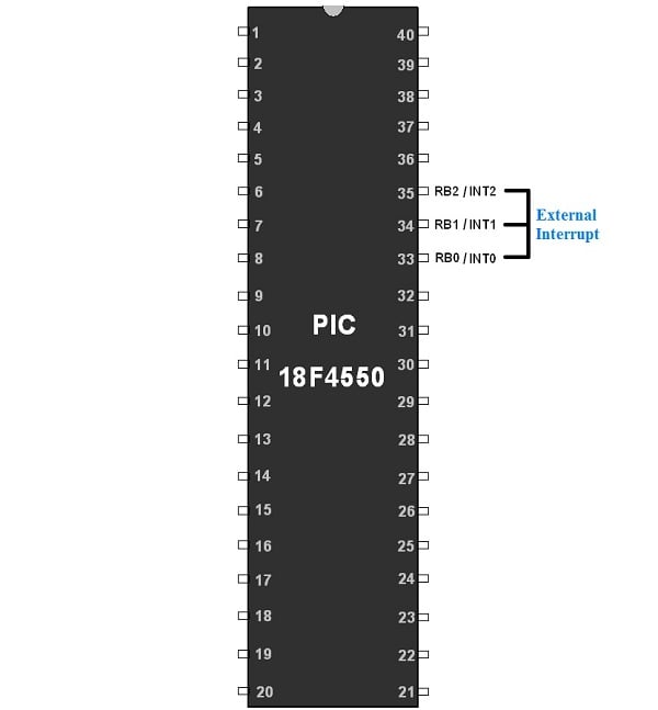
These interrupts are edge-triggered interrupts i.e. triggered by either a rising edge or by a falling edge.
The edge trigger bit is present in an INTCON2 register.
So let’s see the INTCON2 Register.
INTCON2 Register
INTCON2: Interrupt Control Register

INTEDG0: External Interrupt 0 Edge select bit
1= Interrupt on Rising Edge
0= Interrupt on Falling Edge
INTEDG1: External Interrupt 1 Edge select bit
1= Interrupt on Rising Edge
0= Interrupt on Falling Edge
INTEDG2: External Interrupt 2 Edge select bit
1= Interrupt on Rising Edge
0= Interrupt on Falling Edge
RBPU: PORTB Pull-up enable bit
- PORTB has a weak internal pull-up. So to enable them RBPU bit is used.
1= All PORTB Pull-ups are disabled
0= All PORTB Pull-ups are enabled
TMR0IP: TMR0 overflow interrupt Priority
1= High Priority
0= Low Priority
RBIP: RB PORT change Interrupt Priority
1 = High Priority
0 = Low Priority
Steps for Programming
Initialization
- Set PORTB External interrupt pin as an input.
- Also, make PORTB pins as digital input as it is multiplexed with ADC channels. This is done by disabling the ADON bit in the ADCON1 register or by making the PBADEN configuration a bit low.
- Configure INTCON2 register for edge trigger i.e. positive or negative edge.
- Enable external interrupt (INT0, INT1, INT2) by setting a respective interrupt to enable bit in the INTCON register.
- Enable Global Interrupt (GIE).
void External_Interrupt_Init()
{
    TRISBbits.TRISB0=1;		/* Make INT0 pin as an input pin*/

    /* Also make PBADEN off in Configuration file or clear ADON
    in ADCON0 so as to set analog pin as digital*/

    INTCON2=0x00;		/* Set Interrupt detection on falling Edge*/
    INTCONbits.INT0IF=0;	/* Clear INT0IF flag*/
    INTCONbits.INT0IE=1;	/* Enable INT0 external interrupt*/
    INTCONbits.GIE=1;		/* Enable Global Interrupt*/
}
- When an interrupt occurs, it will jump to the ISR to serve to interrupt.
- Finally, clear the Interrupt flag and continue.
Application
We are going to develop a small application on PIC18F4550 using an external interrupt. In this, we will toggle LED which is connected to the PORTC.0 pin when an external interrupt occurs.
Interfacing Diagram
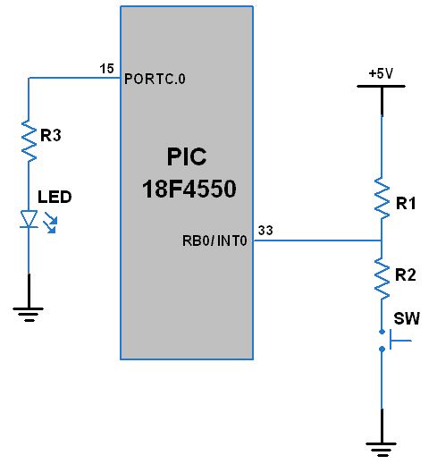
- Here, the external interrupt event is coming from the switch connected to pin PORTB.0 (INT0). This event is a negative edge triggered. When the switch is pressed, a low pulse is generated on the INT0 pin. This will generate an interrupt as the INTCON2 register is configured to detect a negative edge trigger (high to low pulse).
- Then the control will move to the ISR in which the LED on PORTC.0 will toggle and the control will move to the main program.
- So there is no need to poll the PORTB.0 pin continuously.
/*
*Toggle LED using External Interrupt
*www.electronicwings.com
*/
#include "osc.h"
#include <p18f4550.h>

#define LED LATC

void External_Interrupt_Init();
void MSdelay(unsigned int);

void main()
{
    OSCCON=0x72;		/* Set internal oscillator to 8MHz*/
    TRISC0=0;			/* Make PORTC.0 as output*/
    LED=0;
    External_Interrupt_Init();	/* Initialize External Interrupt*/
    while(1);
}

void External_Interrupt_Init()
{
    TRISBbits.TRISB0=1;		/* Make INT0 pin as an input pin*/

    /* Also make PBADEN off in Configuration file or
    clear ADON in ADCON0 so as to set analog pin as digital*/

    INTCON2=0x00;		/* Set Interrupt on falling Edge*/
    INTCONbits.INT0IF=0;	/* Clear INT0IF flag*/
    INTCONbits.INT0IE=1;	/* Enable INT0 external interrupt*/
    INTCONbits.GIE=1;		/* Enable Global Interrupt*/
}


void interrupt ISR()
{
    LED = ~(LED);		/* Toggle LED on interrupt*/
    MSdelay(200);
    INTCONbits.INT0IF=0;
}

void MSdelay(unsigned int val)
{
 unsigned int i,j;
 for (i=0; i<val; i++)
     for (j=0; j<165; j++);	/* Delay count for 1ms for 8MHz freq. */
}
Video
Components Used
Powered by
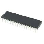

Downloads
Comments8
Join the discussion — share a question or tip.
- AD
Hi all void interrupt ISR(){} //Errors i am getting ledmain.c:106:6: error: variable has incomplete type 'void' void interrupt ISR() ledmain.c:106:15: error: expected ';' after top level declarator void interrupt ISR() 2) if i change it to void __interrupt() ISR(void) { } executed but not working
- AI
void interrupt_ISR()
- GU
Hello, I ve got a problem using interrupts. I want to create an interrupt whenever INT0 = 1. I use a pic 18f4550 As soon as my program has executed the interrupt setting function, it goes directly to the interrupt routine and keeps running the routine. I used the simulator and I saw that the setting function set RB0 to 1. I don't understand why. I use your code to initialise interrupt and PBADEN is OFF in my config. TRISBbits.TRISB0=1; /* Make INT0 pin as an input pin*/ /* Also make PBADEN off in Configuration file or clear ADON in ADCON0 so as to set analog pin as digital*/ INTCON2=0x00; /* Set Interrupt on falling Edge*/ INTCONbits.INT0IF=0; /* Clear INT0IF flag*/ INTCONbits.INT0IE=1; /* Enable INT0 external interrupt*/ INTCONbits.GIE=1; Do you have an idea where the problem comes from? Thank you ! Guillaume