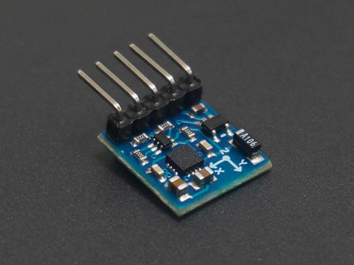
Magnetometer HMC5883L interfacing with PIC18F4550
Magnetometer HMC5883L is developed by Honeywell which gives heading directions. A magnetometer is used as a compass in Mobiles Phones, Navigation systems in vehicles to indicate directions.
Introduction
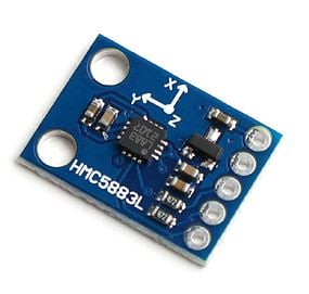
Magnetometer HMC5883L is used for measuring the direction and magnitude of the Earth’s magnetic field. It is used for low cost compassing and magnetometry.
It measures the Earth’s magnetic field value along the X, Y, and Z axes from milli-gauss to 8 gausses.
It can be used to find the direction of the heading of the device.
It uses the I2C protocol for communication with microcontrollers.
For more information about Magnetometer HMC5883L and how to use it, refer to the topic HMC5883L Magnetometer Module in the sensors and modules section.
Programming HMC5883L Magnetometer
Let’s interface magnetometer HMC5883L with PIC18F4550 and calculate its heading angle. HMC5883L uses the I2C protocol for communication. Here we are connecting PIC18F4550 as a master device and HMC5883L as a slave device. Its I2C device address is 0x3C. Its read and write operation addresses are:
Here we are using I2C of PIC18F4550 to communicate with HMC5883L.
Slave device write address (SLA+W): 0x3C
Slave device read address (SLA+R): 0x3D
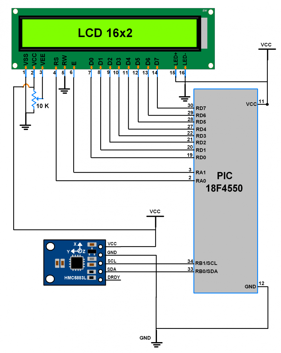
Connection Diagram HMC5883L Magnetometer to PIC18F4550
Programming steps
- First, we need to set configuration register A for an average of 8-sample measurement with 15 Hz default data output rate
- Set Gain using Configuration Register B i.e. here its 0xA0. (or we can choose any other desired gain)
- Select Continuous measurement mode of operation in Mode Register. Hence Mode Register value will become 0x00.
After initialization, write the start location of output data registers X, Y, and Z i.e. 0x03, and read all six registers' raw values.
Calculate Heading value by using the formula,
(in radian)
(in radian)
HMC5883L Magnetometer Code for PIC18F4550
/*
 * Magnetometer interface with PIC18F4550
 * http://electronicwings.com
 *
 */

#include <pic18f4550.h>
#include <stdio.h>
#include <stdlib.h>
#include <math.h>			/* Include math header file */
#include "Configuration_header_file.h"
#include "I2C_Master_File.h"
#include "LCD_16x2_Header_file.h"

#define PI	3.14159265359	/* Define Pi value */
#define Declination	-0.00669
/* Define declination of location from where measurement going to be done. e.g. here we have added declination from location Pune city,India. we can get it from http://www.magnetic-declination.com */

void Magneto_init()			/* Magneto initialize function */
{
	I2C_Start(0x3C);		/* Start and write SLA+W */
	I2C_Write(0x00);		/* Write memory location address */
	/* Configure register A as 8-average, 15 Hz default, normal measurement */
	I2C_Write(0x70);
	I2C_Write(0xA0);		/* Configure register B for gain */
	I2C_Write(0x00);		/* Configure continuous measurement mode */
	I2C_Stop();				/* Stop I2C */
}

int Magneto_GetHeading()
{
	int x, y, z;
	double Heading;
	I2C_Start_Wait(0x3C);				/* Start and wait for acknowledgment */
	I2C_Write(0x03);					/* Write memory location address */
	I2C_Repeated_Start(0x3D);			/* Generate repeat start with SLA+R */

	/* Read 16 bit x,y,z value (2?s complement form) */
	x = (((int)I2C_Read(0)<<8) | (int)I2C_Read(0));
	z = (((int)I2C_Read(0)<<8) | (int)I2C_Read(0));
	y = (((int)I2C_Read(0)<<8) | (int)I2C_Read(1));
	I2C_Stop();							/* Stop I2C */
	Heading = atan2((double)y,(double)x) + Declination;
	if (Heading>2*PI)					/* Due to declination check for >360 degree */
		Heading = Heading - 2*PI;
	if (Heading<0)						/* Check for sign */
		Heading = Heading + 2*PI;
	return ((int)(Heading* 180 / PI));	/* Convert into angle & return */
}


int main(void)
{
	char buffer[25];
	OSCCON = 0x72;		/* Internal Oscillator frequency 8 MHz */
	TRISB &= ~(1<<4);	/* Make pin5 of PORT B as input */
	LCD_Init();			/* Initialize LCD */
	I2C_Init();			/* Initialize I2C */
	Magneto_init();		/* Initialize magneto */
	LCD_String("Magnetometer");
	while (1)
	{
		sprintf(buffer,"Heading = %d%c    ",Magneto_GetHeading(),0xDF);
		LCD_String_xy(2,0,buffer);  /* Print heading on LCD */
	}
}
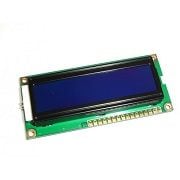
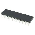
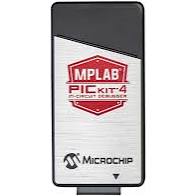
Components Used
Powered by
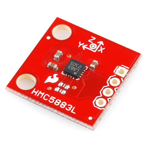
Magnetometer HMC5883L is developed by Honeywell. It gives the heading direction.
909-MOD-HMC5883L
Downloads
Comments3
Join the discussion — share a question or tip.
- IS
I have been using hmc5883l with my pic184550 project but cannot find any good calibration tools. I have been trying mag3110 magnetometer but cannot get it to work with your code here. It hangs at the I2C_start_wait function in magneto_getheading. Any ideas on getting this to work? Also is it possible to set HMC5883L calibration offsets and scales in your code here? Can you suggest some additions?
- AR
About a pullup resistor??