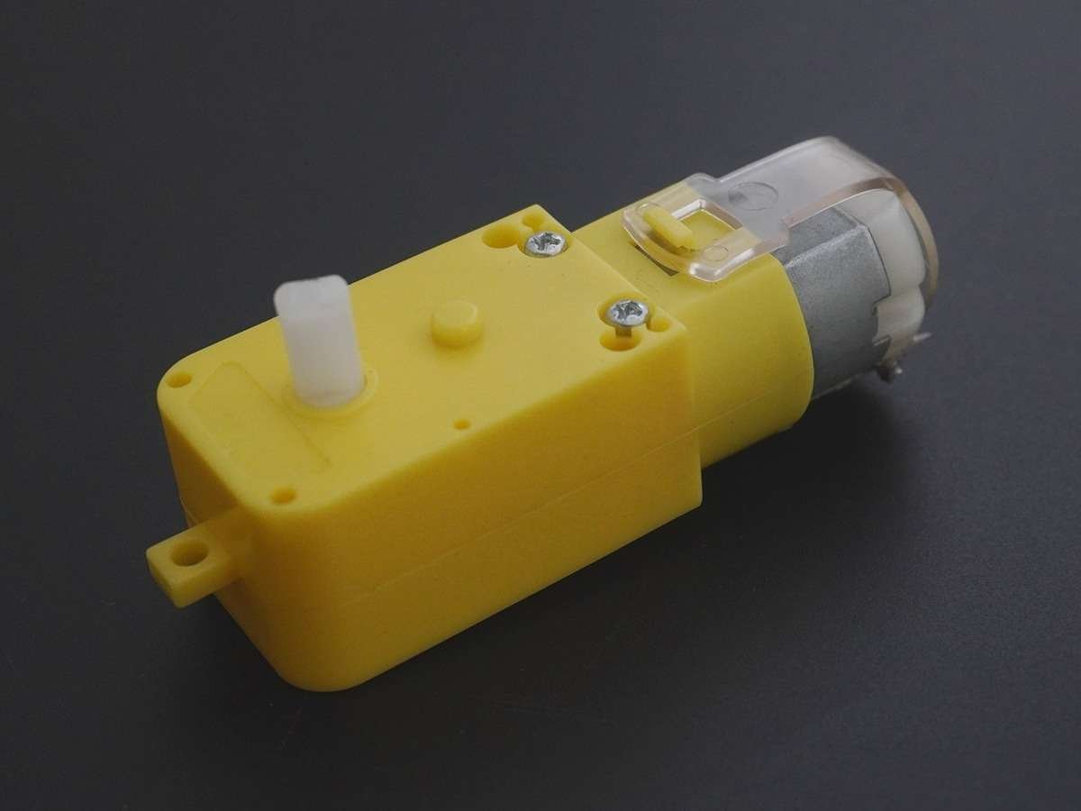
DC motor interfacing with PIC18F4550
DC Motor is a device that converts electrical energy into mechanical energy. It is used in the robotics field, toys, quadcopters etc.
Overview of DC Motor
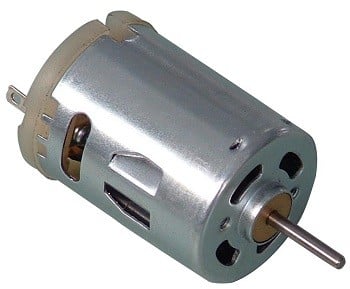
DC motor converts electrical energy in the form of Direct Current into mechanical energy.
- In the case of the motor, the mechanical energy produced is in the form of a rotational movement of the motor shaft.
- The direction of rotation of the shaft of the motor can be reversed by reversing the direction of Direct Current through the motor.
- The motor can be rotated at a certain speed by applying a fixed voltage to it. If the voltage varies, the speed of the motor varies.
- Thus, the DC motor speed can be controlled by applying varying DC voltage; whereas the direction of rotation of the motor can be changed by reversing the direction of current through it.
- For applying varying voltage, we can make use of the PWM technique.
- For reversing the current, we can make use of H-Bridge circuit or motor driver ICs that employ the H-Bridge technique or other any other mechanisms.
For more information about DC motors and how to use them, H-Bridge circuit configuration, PWM technique, refer to the topic DC Motors in the sensors and modules section as well as refer Working Principle of DC motor.
Connection Diagram of DC Motor to PIC18F4550
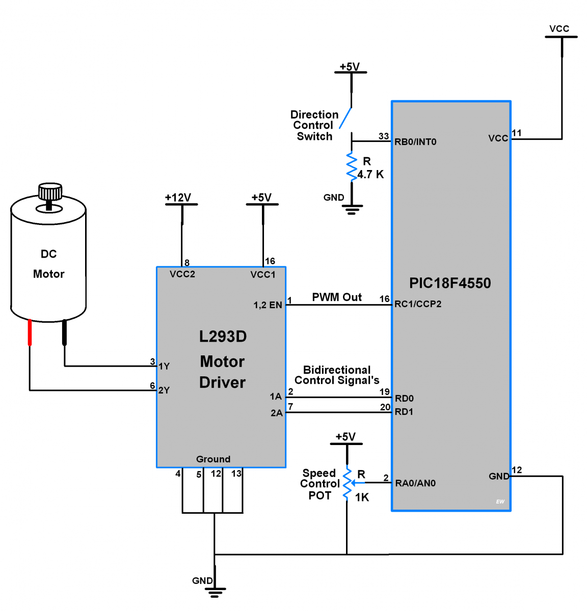
Control the speed of the DC Motor using PIC18F4550
Here, we are going to interface the DC motor with a PIC18F4550 microcontroller. In which we will control the DC motor speed by using POT connected to ADC of PIC18F4550 and direction by using a switch.
We are going to use the L293D motor driver IC to control the DC motor movement in both directions. It has an in-built H-bridge motor drive.
- As shown in the above figure we have connected 1KΩ Potentiometer at ADC channel 0 of PIC18F4550 to change the speed of the DC motor.
- One toggle switch is connected to the INT0 pin which controls the motor rotating direction.
- PORTD is used as an output control signal port. It provides control to motor1 input pins of the L293D motor driver which rotates the motor clockwise and anticlockwise by changing their terminal polarity.
Programming steps
- Enable ADC and map its output into 0-255 range.
- Enable Global interrupt, INT0 external interrupt with a rising edge-triggered mode.
- Set PWM mode.
- Vary Duty cycle with ADC value and in an interrupt routine, we are toggling motor direction.
- Now continuously check for an interrupt for direction and read the ADC value for speed control.
- A switch will produce interrupt which causes to change in motor direction.
DC Motor Speed Control Code using PIC18F4500
/*
 * DC Motor Speed & Direction control using PIC18F4550
 * http://www.electronicwings.com
 */


#include <math.h>
#include <stdio.h>
#include <pic18f4550.h>
#include "ADC_Header_File.h"
#include "Configuration_header_file.h"

#define MINTHR              8000
#define RESOLUTION          488

#define InternalOsc_8MHz    8000000
#define InternalOsc_4MHz    4000000
#define InternalOsc_2MHz    2000000
#define InternalOsc_1MHz    1000000
#define InternalOsc_500KHz  500000
#define InternalOsc_250KHz  250000
#define InternalOsc_125KHz  125000
#define InternalOsc_31KHz   31000

#define Timer2Prescale_1    1
#define Timer2Prescale_4    4
#define Timer2Prescale_16   16

void MSdelay(unsigned int val)
{
 unsigned int i,j;
 for (i=0; i<=val; i++)
     for (j=0; j<165; j++); /* Delay count for 1ms for 8MHz freq. */
}

void PWM_Init()             /* Initialize PWM */
{
    TRISCbits.TRISC1 = 0;   /* Set CCP2 pin as output for PWM out */
    CCP2CON = 0x0C;         /* Set PWM mode */
}

int setPeriodTo(unsigned long FPWM)/* Set period */
{
    int clockSelectBits, TimerPrescaleBits;
    int TimerPrescaleValue;
    float period;
    unsigned long FOSC, _resolution = RESOLUTION;

    if (FPWM < MINTHR)    {TimerPrescaleBits = 2; TimerPrescaleValue = Timer2Prescale_16;}
    else                  {TimerPrescaleBits = 0; TimerPrescaleValue = Timer2Prescale_1;}

    if (FPWM > _resolution)               {clockSelectBits = 7; FOSC = InternalOsc_8MHz;}
    else if (FPWM > (_resolution >>= 1))  {clockSelectBits = 6; FOSC = InternalOsc_4MHz;}
    else if (FPWM > (_resolution >>= 1))  {clockSelectBits = 5; FOSC = InternalOsc_2MHz;}
    else if (FPWM > (_resolution >>= 1))  {clockSelectBits = 4; FOSC = InternalOsc_1MHz;}
    else if (FPWM > (_resolution >>= 1))  {clockSelectBits = 3; FOSC = InternalOsc_500KHz;}
    else if (FPWM > (_resolution >>= 1))  {clockSelectBits = 2; FOSC = InternalOsc_250KHz;}
    else if (FPWM > (_resolution >>= 1))  {clockSelectBits = 1; FOSC = InternalOsc_125KHz;}
    else                                  {clockSelectBits = 0; FOSC = InternalOsc_31KHz;}

    period = ((float)FOSC / (4.0 * (float)TimerPrescaleValue * (float)FPWM)) - 1.0;
    period = round(period);

    OSCCON = ((clockSelectBits & 0x07) << 4) | 0x02;
    PR2 = (int)period;
    T2CON = TimerPrescaleBits;
    TMR2 = 0;
    T2CONbits.TMR2ON = 1;  /* Turn ON Timer2 */
    return (int)period;
}

void SetDutyCycleTo(float Duty_cycle, int Period)/* Set Duty cycle for given period */
{
    int PWM10BitValue;

    PWM10BitValue = 4.0 * ((float)Period + 1.0) * (Duty_cycle/100.0);
    CCPR2L = (PWM10BitValue >> 2);
    CCP2CON = ((PWM10BitValue & 0x03) << 4) | 0x0C;
}

void External_Interrupt_Init()
{
    TRISBbits.TRISB0=1;		/* Make INT0 pin as an input pin*/

    /* Also make PBADEN off in Configuration file or
    clear ADON in ADCON0 so as to set analog pin as digital*/

    INTCON2 = 0x40;         	/* Set Interrupt on Rising Edge*/
    INTCONbits.INT0IF = 0;	/* Clear INT0IF flag*/
    INTCONbits.INT0IE = 1;	/* Enable INT0 external interrupt*/
    INTCONbits.GIE = 1;		/* Enable Global Interrupt*/
}
void interrupt ISR()
{
    LATD0 = ~LATD0;         	/* Change direction of DC Motor */
    LATD1 = ~LATD1;
    MSdelay(300);
    INTCONbits.INT0IF=0;
}

void main(void)
{
    float Duty_Scale;
    int Period;

    TRISD = 0x00;           	/* PORTD as output */
    LATD0 = 0;              	/* Initial Direction */
    LATD1 = 1;
    ADC_Init();
    PWM_Init();             	/* Initialize PWM */
    External_Interrupt_Init();
    Period = setPeriodTo(10000);/* 10KHz PWM frequency */
    /* Note that period step size will gradually increase with PWM frequency */
    while(1)
    {
        Duty_Scale = (((float)(ADC_Read(0)/4.0))/2.55); /* Scale Duty Cycle */
        SetDutyCycleTo(Duty_Scale, Period);
    }
}
Video DC Motor Speed Control using PIC18F4550
Components Used
Powered by
Downloads
Comments7
Join the discussion — share a question or tip.
- UL
Hey bro.can i get the circuit diagram to run to simulation first?
- IS
Hi OSCCON = ((clockSelectBits & 0x07) << 4) | 0x02; I am interested in the effects of the above statement in my project. If I am also controlling some additional device eg. I have a gps module that stops working when I use the setPeriod() function. Forgive my lack of knowledge on pic controllers but are you changing the internal oscillator value (8 MHz) to a slower rate?