External Hardware Interrupts in AVR ATmega16/ATmega32
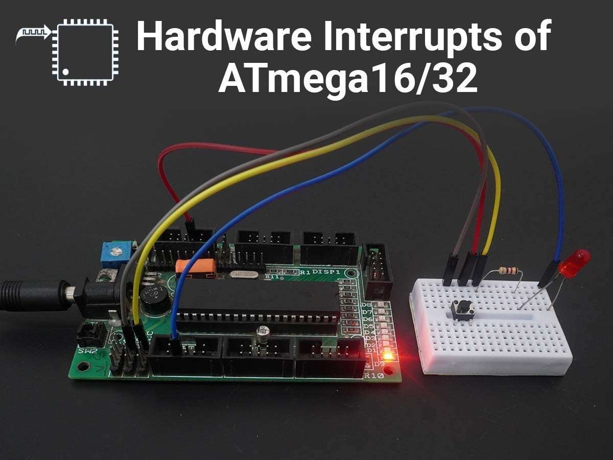
AVR ATmega16/ATmega32 External Interrupts feature provides a way to get noticed by external events.
Introduction to Interrupt
AVR ATmega16/ATmega32 has three external hardware interrupts on pins PD2, PD3, and PB2 which are referred to as INT0, INT1, and INT2 respectively. Upon activation of these interrupts, the ATmega controller gets interrupted in whatever task it is doing and jumps to perform the interrupt service routine.
External interrupts can be level-triggered or edge-triggered. We can program this triggering. INT0 and INT1 can be level-triggered and edge-triggered whereas INT2 can be only edge-triggered.
Programming External Interrupt Register
We can enable/disable external interrupts by the GICR register.

- Bit 7 – INT1: External Interrupt Request 1 Enable
0: Disable external interrupt
1: Enable external interrupt
- Bit 6 – INT0: External Interrupt Request 0 Enable
0: Disable external interrupt
1: Enable external interrupt
- Bit 5 – INT2: External Interrupt Request 2 Enable
0: Disable external interrupt
1: Enable external interrupt
MCU Control Register (MCUCR)
To define a level trigger or edge trigger on external INT0 and INT1 pins MCUCR register is used.

ISC01, ISC00 (Interrupt Sense Control bits)
These bits define the level or edge that triggers the INT0 pin.
| ISC01 | ISC00 | Description | |
|---|---|---|---|
| 0 | 0 |  | The low level on the INT0 pin generates an interrupt request. |
| 0 | 1 |  | Any logical change on the INT0 pin generates an interrupt request. |
| 1 | 0 |  | The falling edge on the INT0 pin generates an interrupt request. |
| 1 | 1 |  | The rising edge on the INT0 pin generates an interrupt request. |
ISC11, ISC10 (Interrupt Sense Control bits)
These bits define the level or edge that triggers the INT1 pin.
| ISC01 | ISC00 | Description | |
|---|---|---|---|
| 0 | 0 | | The low level on the INT1 pin generates an interrupt request. |
| 0 | 1 | | Any logical change on the INT1 pin generates an interrupt request. |
| 1 | 0 | | The falling edge on the INT1 pin generates an interrupt request. |
| 1 | 1 | | The rising edge on the INT1 pin generates an interrupt request. |
MCU Control and Status Register (MCUCSR)
To define the INT2 interrupt activity, bit 6 of MCUCSR is used.

ISC2 bit defines the INT2 interrupt triggering.
| ISC2 | Description | |
|---|---|---|
| 0 | | The falling edge on the INT2 pin generates an interrupt request. |
| 1 | | The rising edge on the INT2 pin generates an interrupt request. |
Application
Toggle the LED connected on PORTC using external interrupt INT0 (PORTD 2).
ATmega16/32 external interrupt Code
/*
	ATmega16 external interrupt to toggle the PORTC
	(www.electronicwings.com)
*/


#define F_CPU 8000000UL
#include <avr/io.h>
#include <avr/interrupt.h>
#include <util/delay.h>

/*Interrupt Service Routine for INT0*/
ISR(INT0_vect)
{
	PORTC=~PORTC;		/* Toggle PORTC */
	_delay_ms(50);  	/* Software debouncing control delay */

}

int main(void)
{
	DDRC=0xFF;		/* Make PORTC as output PORT*/
	PORTC=0;
	DDRD=0;			/* PORTD as input */
	PORTD=0xFF;		/* Make pull up high */

	GICR = 1<<INT0;		/* Enable INT0*/
	MCUCR = 1<<ISC01 | 1<<ISC00;  /* Trigger INT0 on rising edge */

	sei();			/* Enable Global Interrupt */

	while(1);
}
Tips
- In interrupts (falling edge, rising edge, and level change interrupts), the pulse must be at least 1 instruction cycle to ensure the transition seen by the microcontroller. Means, pulse shorter than 1 machine cycle will not guarantee an interrupt.
- When an external interrupt is level triggered, the pin must be held low for a minimum time of 5 machine cycles to recognize.
- In various applications, an external interrupt may be used for detecting push-button activity from the user as the push button switch is connected to take input. In this case, it is always better to use low-level triggered interrupt and give some de-bouncing delay to avoid multiple occurrences of an interrupt at the same time.
Video
Components Used
Powered by
Downloads
Comments4
Join the discussion — share a question or tip.
- MU
the populat atmega 328P mcu there is only two interrupts in portD. External interrupt mask register (EIMSK) will be used to select interrupt pin and External interrupt control register (EICRA) will be used for controlling.
- SA
hi sir, Thanks for such wonderful knowledge. i have a question here, is it possible to nest interrupts. Is it possible to wait for another interrupt inside another ISR. Kind Regards
- LO
we can use a nested interrupt. When we use nested interrupt then they depends on interrupt priority. Current execution of ISR will get halt if another interrupt occurs with the highest priority. But it is now good to poll an interrupt inside ISR. You can create multiple ISR according to their vector address and nest an interrupt if required.