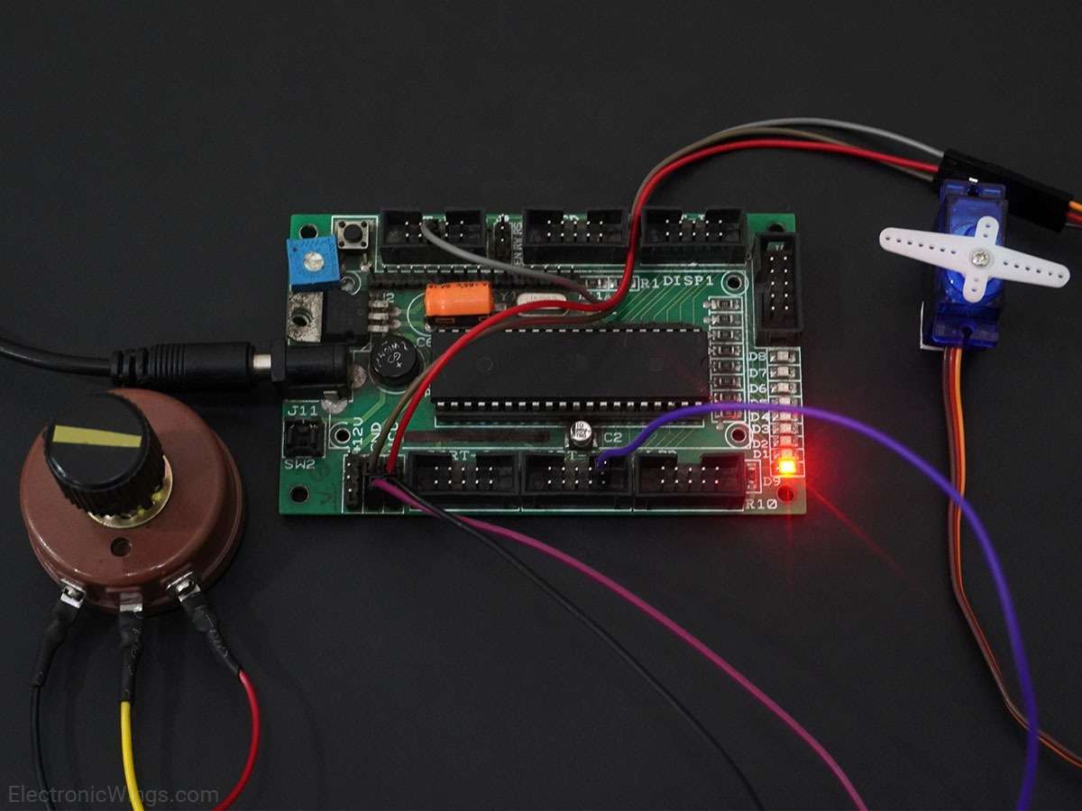
PWM in AVR ATmega16/ATmega32
AVR-based ATmega16/32 has inbuilt Pulse Width Modulation (PWM) unit through which the width of a pulse is varied while keeping the frequency constant.
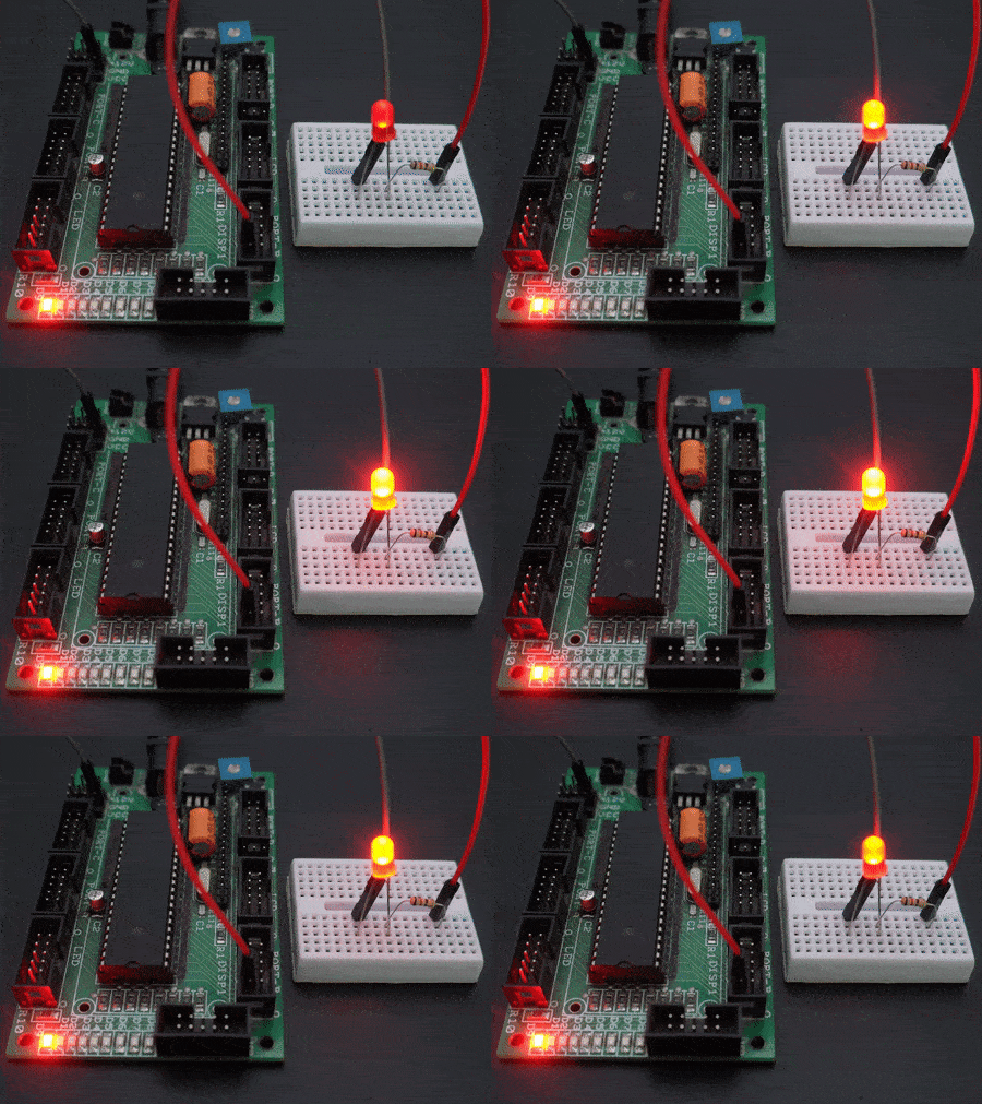
Introduction to PWM
Pulse Width Modulation (PWM) is a technique by which the width of a pulse is varied while keeping the frequency constant.
Why do we need to do this? Let’s take an example of controlling DC motor speed, more the Pulse width more the speed. Also, there are applications like controlling light intensity by PWM.
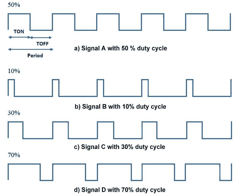
A period of a pulse consists of an ON cycle (5V) and an OFF cycle (0V). The fraction for which the signal is ON over a period is known as the duty cycle.
Duty Cycle (In %) =
E.g. Consider a pulse with a period of 10ms which remains ON (high) for 2ms.The duty cycle of this pulse will be
D = 2ms / 10ms = 20%
Through the PWM technique, we can control the power delivered to the load by using the ON-OFF signal.
Pulse Width Modulated signals with different duty cycle are shown below
AVR ATmega PWM
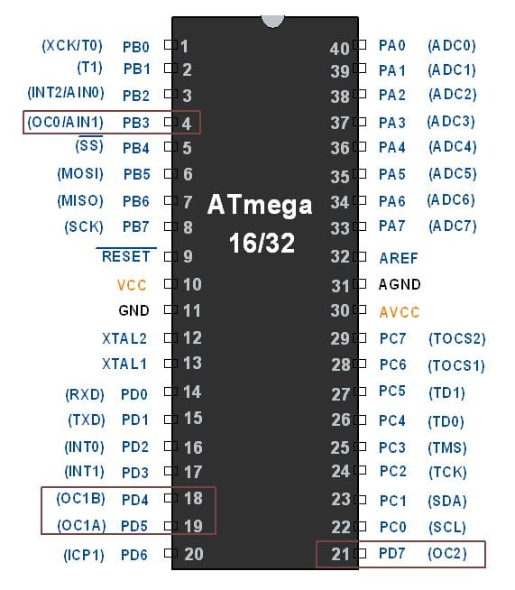
ATmega has an inbuilt PWM unit. As we know, ATmega has 3 Timers T0, T1, and T2 which can be used for PWM generation. Mainly there are two modes in PWM.
- Fast PWM
- Phase correct PWM
We need to configure the Timer Register for generating PWM. PWM output will be generated on the corresponding Timer’s output compare pin (OCx).
Configuring Timer0 for PWM generation
It is simple to configure PWM mode in Timer. We just need to set some bits in the TCCR0 register.
TCCR0: Timer Counter Control Register 0

Bit 7- FOC0: Force compare match
Write only bit, which can be used while generating a wave. Writing 1 to this bit will force the wave generator to act as if a compare match has occurred.
Bit 6, 3 - WGM00, WGM01: Waveform Generation Mode
| WGM00 | WGM01 | Timer0 mode selection bit |
|---|---|---|
| 0 | 0 | Normal |
| 0 | 1 | CTC (Clear timer on Compare Match) |
| 1 | 0 | PWM, Phase correct |
| 1 | 1 | Fast PWM |
Bit 5:4 - COM01:00:
- When WGM00: WGM01= 11 i.e. Fast PWM. Compare Output Mode
waveform generator on OC0 pin
| COM01 | COM00 | Mode Name | Description |
|---|---|---|---|
| 0 | 0 | Disconnected | The normal port operation, OC0 disconnected |
| 0 | 1 | Reserved | Reserved |
| 1 | 0 | Non-inverted | Clear OC0 on compare match, set OC0 at TOP |
| 1 | 1 | Inverted PWM | Set OC0 on compare match, clear OC0 at TOP |
2. When WGM00: WGM01= 10 i.e. Phase correct PWM. Compare Output Mode
waveform generator on OC0 pin
| COM01 | COM00 | Description |
|---|---|---|
| 0 | 0 | The normal port operation, OC0 disconnected |
| 0 | 1 | Reserved |
| 1 | 0 | Clear OC0 on compare match when up-counting, set OC0 on compare match when down-counting |
| 1 | 1 | Set OC0 on compare match when up-counting, Clear OC0 on compare match when down-counting |
Bit 2:0 - CS02:CS00: Clock Source Select
These bits are used to select a clock source. When CS02: CS00 = 000, then timer is stopped. As it gets a value between 001 to 101, it gets a clock source and starts as the timer.
| CS02 | CS01 | CS00 | Description |
|---|---|---|---|
| 0 | 0 | 0 | No clock source (Timer / Counter stopped) |
| 0 | 0 | 1 | clk (no pre-scaling) |
| 0 | 1 | 0 | clk / 8 |
| 0 | 1 | 1 | clk / 64 |
| 1 | 0 | 0 | clk / 256 |
| 1 | 0 | 1 | clk / 1024 |
| 1 | 1 | 0 | External clock source on T0 pin. clock on falling edge |
| 1 | 1 | 1 | External clock source on T0 pin. clock on rising edge. |
Fast PWM mode
To set Fast PWM mode, we have to set WGM00: 01= 11. To generate a PWM waveform on the OC0 pin, we need to set COM01:00= 10 or 11.
COM01:00= 10 will generate Noninverting PWM output waveform and COM01:00= 11 will generate Inverting PWM output waveform. See fig.
void PWM_init()
{
	/*set fast PWM mode with non-inverted output*/
	TCCR0 = (1<<WGM00) | (1<<WGM01) | (1<<COM01) | (1<<CS00);
	DDRB|=(1<<PB3);  /*set OC0 pin as output*/
}
Setting Duty cycle: we have to load value in the OCR0 register to set the duty cycle.
255 value for 100% duty cycle and 0 for 0% duty cycle. Accordingly, if we load value 127 in OCR0, the Duty cycle will be 50%.
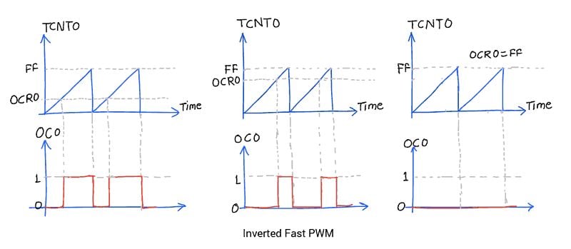
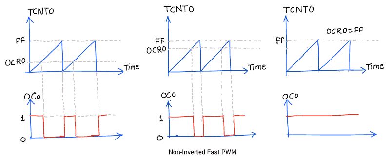
The advantage of using PWM mode in AVR is that it is an inbuilt hardware unit for waveform generation and once we set the PWM mode and duty cycle, this unit starts generating PWM and the controller can do other work.
Example
Control LED brightness using Fast PWM.
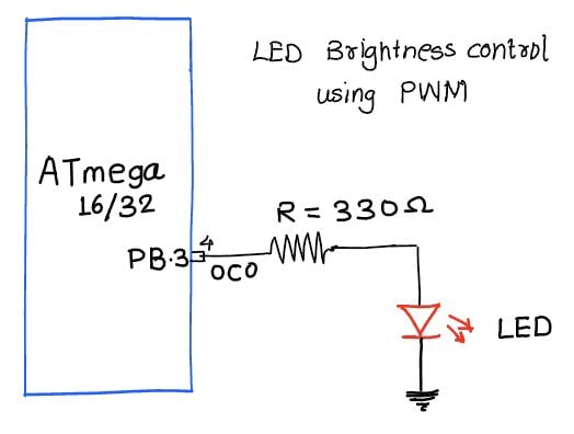
/*
   AVR ATmega16 PWM to control LED brightness
   http://www.electronicwings.com
*/

#define F_CPU 8000000UL
#include "avr/io.h"
#include <util/delay.h>


void PWM_init()
{
	/*set fast PWM mode with non-inverted output*/
	TCCR0 = (1<<WGM00) | (1<<WGM01) | (1<<COM01) | (1<<CS00);
	DDRB|=(1<<PB3);  /*set OC0 pin as output*/
}


int main ()
{
	unsigned char duty;

	PWM_init();
	while (1)
	{
		for(duty=0; duty<255; duty++)
		{
			OCR0=duty;  /*increase the LED light intensity*/
			_delay_ms(8);
		}
		for(duty=255; duty>1; duty--)
		{
			OCR0=duty;  /*decrease the LED light intensity*/
			_delay_ms(8);
		}
	}
}
Phase correct PWM mode
To set Phase correct PWM, we just have to set the TCCRO register as follows.
We can set the output waveform as inverted or non-inverted. See fig.
TCCR0 = (1<<WGM00) | (1<<COM01) | (1<<CS00);
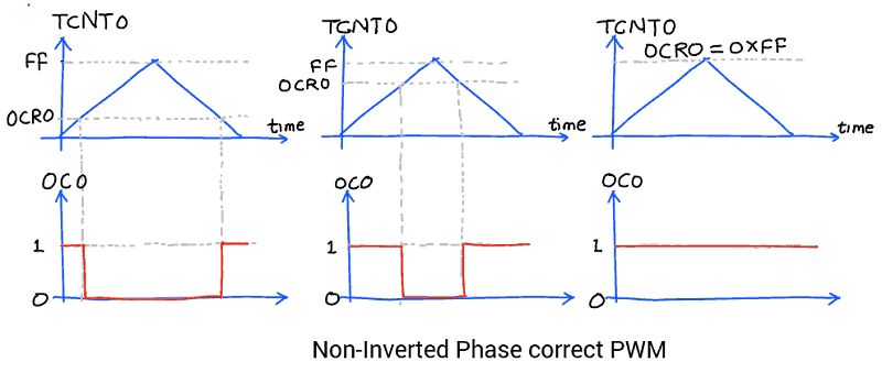
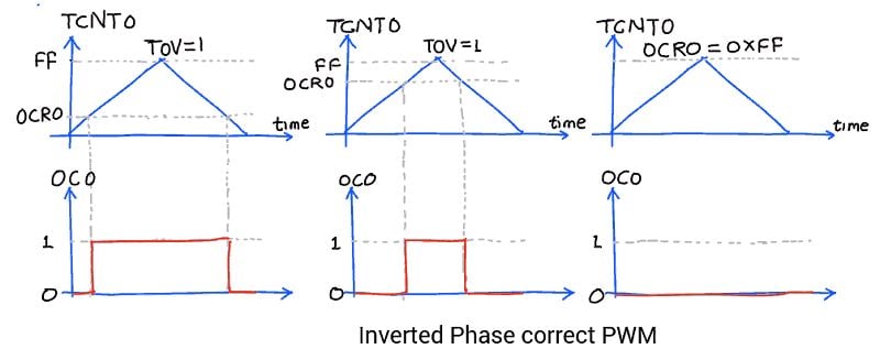
Similarly, we can set PWM output on the other three OCx pins using Timer1 and Timer2.
PWM output is somehow close to the Analog output. We can use it as analog output for generating sine wave, audio signals, etc. it is also referred to as DDS.
Video
Components Used
Powered by
Downloads
Comments15
Join the discussion — share a question or tip.
- NI
Most likely it's obvious to you but you forgot to mention (take me some time to figure out): The Frequency of the fast PWM can be calculated by the following equation: PWM_fequency = clock_speed / (Prescaller_value * 256) In this case Prescaller_value is 1 so PWM fequency is 31250Hz Great tutorial by the way, thank you for sharing.
- JA
How can I set the ocr1a value in fast pwm
- TR
void setup(){ DDRB |= (1<<PB1)|(1<<PB2);// pin 9 and 10 output TCCR1A = 0; TCCR1B = 1; // Clear OC1A and OC1B on Compare Match / Set OC1A and OC1B at Bottom; // Wave Form Generator: Fast PWM 14, Top = ICR1 TCCR1A = (1<<COM1A1) + (1<<COM1A0) + (1<<WGM11); TCCR1B = (1<<WGM13) + (1<<WGM12) + (1<<CS10); // prescaler = 1 (none) OCR1A = 89; OCR1B = 89; } void loop() { // do something else analogWrite(9,OCR1A); analogWrite(10,OCR1B); }
- UZ
what is mean by reserved??
- GO
What's use of difference between fast PWM and phase correct
- GO
Sir I'm having confusion of this for Atmega 328P as it have way more PWM pins than 16 and 32?
- AM
I need someone to explain this to me for an example if want to create a wave of frequency 1khz with duty 50% using a 4mhz clock how can it be done i do understand the duty part , but how to produce a 1 khz using the 4mhz using pwm mode .can it be done without using the top value function for timer 1 ??
- RA
Sir, the article is extremely helpful for beginners like me. In the codes above, some bits which need not be set, like TCCR0 = (1<<WGM00) | (1<<WGM01) | (1<<COM01) | (1<<CS00); to set in Fast PWM, non-inverting mode, COM00 has to be 0, but we have not mentioned in code. Is it possible that it might remain or become 1, where it becomes Inverted? Also, kindly tell which is the CS0 pin, and why we had not mentioned CS02, CS01. Thanks, Ramen
- AU
hello ramen, there is no need to mention COM00 as 0 in code when we mentions other bits that need to set 1 since we are assigning it directly to timer control register. and CS00, CS01, CS02 are bits in TCCR register (not pins) as mentioned in above doc.