Graphical LCD 128x64 interfacing with AVR ATmega16/ATmega32.
GLCD 128x64 is a graphical LCD with pixel resolution 128x64. GLCD 128x64 generally used for displaying text in different fonts, displaying Images, animation, and symbols.
Overview of GLCD 128x64
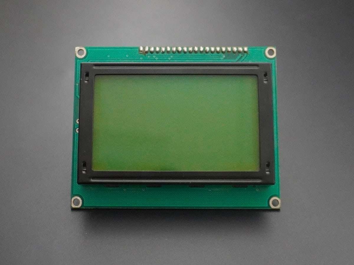
GLCD is a display device that can be used in embedded systems for displaying data and/or images/custom characters.
- Basically, a 128x64 Graphical LCD is a matrix of pixels.
- Each pixel is accessed by their X and Y address.
- We can simply visualize any pixel by making its value HIGH (1).
Hence, we can make any graphical design pixel by pixel using GLCD.
To get familiar with GLCD pins and their functions refer to GLCD 128x64.
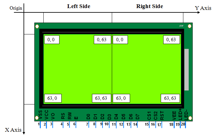
Programming GLCD
Let's program the AVR ATmega16 microcontroller to print text characters on GLCD JHD12864E.
Initialization
To initialize the display, we need to do the below steps,
- Send Display OFF command i.e. 0x3E
- Send Y address e.g. here 0x40 (Start address).
- Send X address (Page) e.g. here 0xB8 (Page0).
- Send Z address (Start line) e.g. here 0xC0 (from 0th line).
- Now send Display ON command i.e. 0x3F
GLCD_Init function
Input arguments: It has no input arguments.
Return type: It does not return any data type.
void GLCD_Init()			/* GLCD initialize function */
{
	Data_Port_Dir = 0xFF;
	Command_Port_Dir = 0xFF;
	/* Select both left & right half of display & Keep reset pin high */
	Command_Port |= (1 << CS1) | (1 << CS2) | (1 << RST);
	_delay_ms(20);
	GLCD_Command(0x3E);		/* Display OFF */
	GLCD_Command(0x40);		/* Set Y address (column=0) */
	GLCD_Command(0xB8);		/* Set x address (page=0) */
	GLCD_Command(0xC0);		/* Set z address (start line=0) */
	GLCD_Command(0x3F);		/* Display ON */
}
Command Write
To write a command do the below steps
- Send command on data pins.
- Make RS = 0 (Command Register) and RW = 0 (Write Operation).
- Make High to Low transition on Enable pin of min. 1us period.
GLCD_Command function
Input arguments: It has an input argument of Command.
Return type: It does not return any data type.
void GLCD_Command(char Command)		/* GLCD command function */
{
	Data_Port = Command;		/* Copy command on data pin */
	Command_Port &= ~(1 << RS);	/* Make RS LOW for command register*/
	Command_Port &= ~(1 << RW);	/* Make RW LOW for write operation */
	Command_Port |=  (1 << EN);	/* HIGH-LOW transition on Enable */
	_delay_us(5);
	Command_Port &= ~(1 << EN);
	_delay_us(5);
}
Data Write
To write data do the below commands
- Send Data on data pins.
- Make RS = 1 (Data Register) and RW = 0 (Write Operation).
- Make High to Low transition on Enable pin of min 1 us period.
GLCD_Data function
Input arguments: It has input argument Data.
Return type: It does not return any data type.
void GLCD_Data(char Data)		/* GLCD data function */
{
	Data_Port = Data;		/* Copy data on data pin */
	Command_Port |=  (1 << RS);	/* Make RS HIGH for data register */
	Command_Port &= ~(1 << RW);	/* Make RW LOW for write operation */
	Command_Port |=  (1 << EN);	/* HIGH-LOW transition on Enable */
	_delay_us(5);
	Command_Port &= ~(1 << EN);
	_delay_us(5);
}
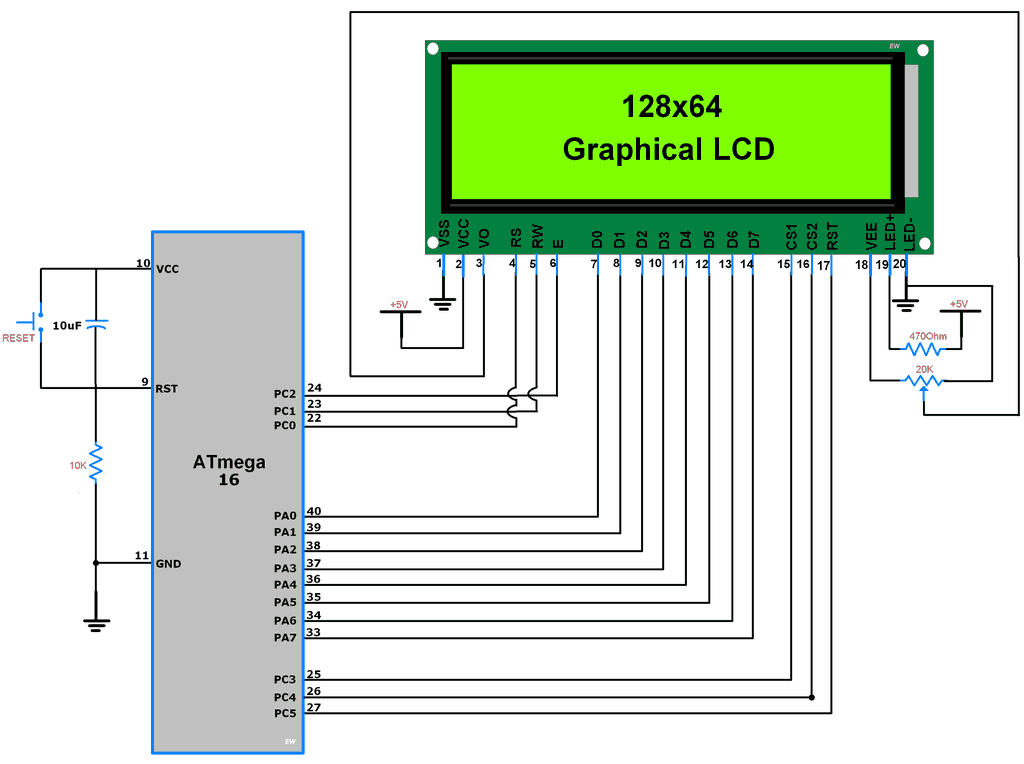
Connection Diagram of GLCD 128x64 with ATmega16/32
Code for Text Print on GLCD using ATmega16/32
/*
 * ATmega_GLCD_TextFont
 * http://electronicwings.com
 */

#define F_CPU 8000000UL			/* Define CPU clock Freq 8MHz */
#include <avr/io.h>			/* Include AVR std. library file */
#include <util/delay.h>			/* Include delay header file */
#include <stdio.h>			/* Include std i/o library file */
#include "Font_Header.h"

#define Data_Port	 PORTA		/* Define data port for GLCD */
#define Command_Port	 PORTC		/* Define command port for GLCD */
#define Data_Port_Dir	 DDRA		/* Define data port for GLCD */
#define Command_Port_Dir DDRC		/* Define command port for GLCD */

#define RS		 PC0		/* Define control pins */
#define RW		 PC1
#define EN		 PC2
#define CS1		 PC3
#define CS2		 PC4
#define RST		 PC5

#define TotalPage	 8

void GLCD_Command(char Command)		/* GLCD command function */
{
	Data_Port = Command;		/* Copy command on data pin */
	Command_Port &= ~(1 << RS);	/* Make RS LOW for command register*/
	Command_Port &= ~(1 << RW);	/* Make RW LOW for write operation */
	Command_Port |=  (1 << EN);	/* HIGH-LOW transition on Enable */
	_delay_us(5);
	Command_Port &= ~(1 << EN);
	_delay_us(5);
}

void GLCD_Data(char Data)		/* GLCD data function */
{
	Data_Port = Data;		/* Copy data on data pin */
	Command_Port |=  (1 << RS);	/* Make RS HIGH for data register */
	Command_Port &= ~(1 << RW);	/* Make RW LOW for write operation */
	Command_Port |=  (1 << EN);	/* HIGH-LOW transition on Enable */
	_delay_us(5);
	Command_Port &= ~(1 << EN);
	_delay_us(5);
}

void GLCD_Init()			/* GLCD initialize function */
{
	Data_Port_Dir = 0xFF;
	Command_Port_Dir = 0xFF;
	/* Select both left & right half of display & Keep reset pin high */
	Command_Port |= (1 << CS1) | (1 << CS2) | (1 << RST);
	_delay_ms(20);
	GLCD_Command(0x3E);		/* Display OFF */
	GLCD_Command(0x40);		/* Set Y address (column=0) */
	GLCD_Command(0xB8);		/* Set x address (page=0) */
	GLCD_Command(0xC0);		/* Set z address (start line=0) */
	GLCD_Command(0x3F);		/* Display ON */
}

void GLCD_ClearAll()			/* GLCD all display clear function */
{
	int i,j;
	/* Select both left & right half of display */
	Command_Port |= (1 << CS1) | (1 << CS2);
	for(i = 0; i < TotalPage; i++)
	{
		GLCD_Command((0xB8) + i);/* Increment page */
		for(j = 0; j < 64; j++)
		{
			GLCD_Data(0);	/* Write zeros to all 64 column */
		}
	}
	GLCD_Command(0x40);		/* Set Y address (column=0) */
	GLCD_Command(0xB8);		/* Set x address (page=0) */
}

void GLCD_String(char page_no, char *str)/* GLCD string write function */
{
	unsigned int i, column;
	unsigned int Page = ((0xB8) + page_no);
	unsigned int Y_address = 0;
	float Page_inc = 0.5;

	Command_Port |= (1 << CS1);	/* Select Left half of display */
	Command_Port &= ~(1 << CS2);

	GLCD_Command(Page);
	for(i = 0; str[i] != 0; i++)	/* Print char in string till null */
	{
		if (Y_address > (1024-(((page_no)*128)+FontWidth)))
		break;
		if (str[i]!=32)
		{
			for (column=1; column<=FontWidth; column++)
			{
				if ((Y_address+column)==(128*((int)(Page_inc+0.5))))
				{
					if (column == FontWidth)
					break;
					GLCD_Command(0x40);
					Y_address = Y_address + column;
					Command_Port ^= (1 << CS1);
					Command_Port ^= (1 << CS2);
					GLCD_Command(Page + Page_inc);
					Page_inc = Page_inc + 0.5;
				}
			}
		}
		if (Y_address>(1024-(((page_no)*128)+FontWidth)))
		break;
		if((font[((str[i]-32)*FontWidth)+4])==0 || str[i]==32)
		{
			for(column=0; column<FontWidth; column++)
			{
				GLCD_Data(font[str[i]-32][column]);
				if((Y_address+1)%64==0)
				{
					Command_Port ^= (1 << CS1);
					Command_Port ^= (1 << CS2);
					GLCD_Command((Page+Page_inc));
					Page_inc = Page_inc + 0.5;
				}
				Y_address++;
			}
		}
		else
		{
			for(column=0; column<FontWidth; column++)
			{
				GLCD_Data(font[str[i]-32][column]);
				if((Y_address+1)%64==0)
				{
					Command_Port ^= (1 << CS1);
					Command_Port ^= (1 << CS2);
					GLCD_Command((Page+Page_inc));
					Page_inc = Page_inc + 0.5;
				}
				Y_address++;
			}
			GLCD_Data(0);
			Y_address++;
			if((Y_address)%64 == 0)
			{
				Command_Port ^= (1 << CS1);
				Command_Port ^= (1 << CS2);
				GLCD_Command((Page+Page_inc));
				Page_inc = Page_inc + 0.5;
			}
		}
	}
	GLCD_Command(0x40);	/* Set Y address (column=0) */
}

int main(void)
{
	GLCD_Init();		/* Initialize GLCD */
	GLCD_ClearAll();	/* Clear all GLCD display */
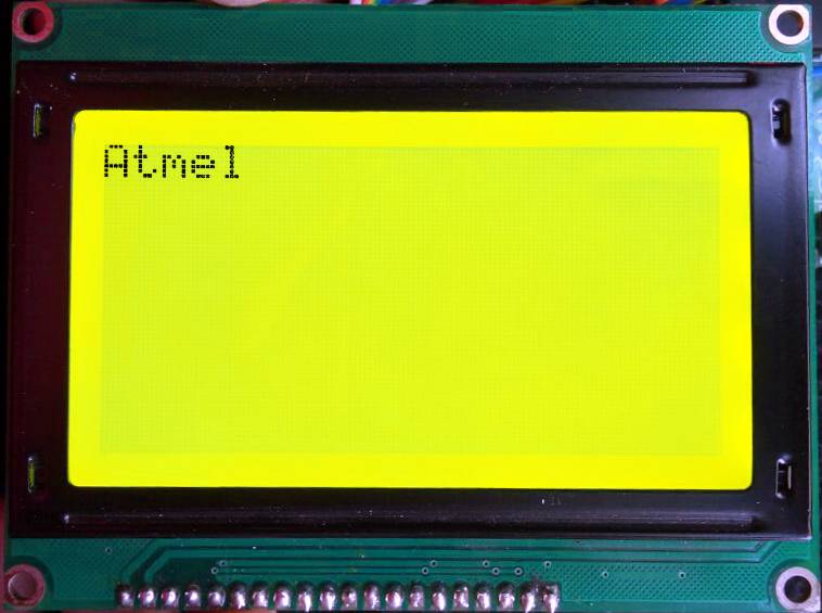
	GLCD_String(0,"Atmel");	/* Print String on 0th page of display */
	while(1);
}
Output Image
Programming AVR ATmega16 to Display Image on GLCD
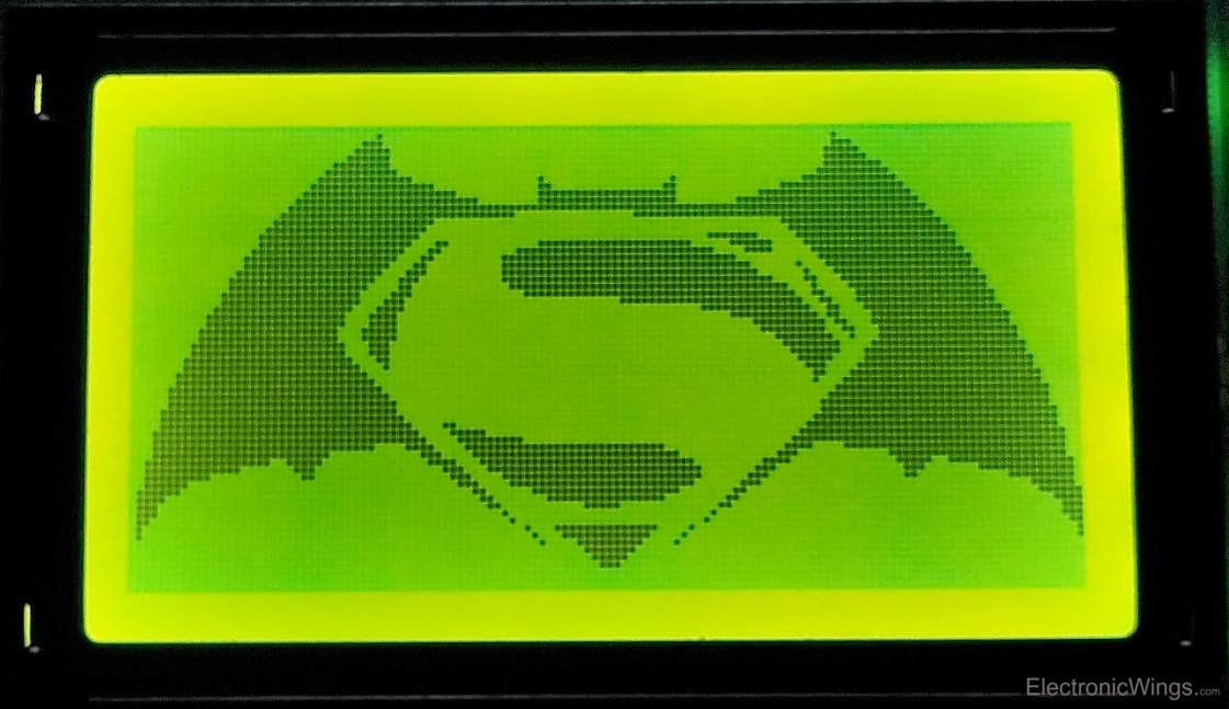
We are using the same functions that are used for displaying text except for the GLCD_String function, which is modified here to print image data on GLCD.
- Binary Image is of a total size of 128x64 pixels. So we need an array of 1024 bytes [(128*64)/8=1024 bytes] to store the image in the microcontroller.
- ATmega16 has 1K bytes of RAM and 16K bytes of Program memory, hence we are storing the image array in program memory.
- To store the image array in the program memory of ATmega16 we need to include below header file in Atmel Studio
#include <avr/pgmspace.h>- The above header file consists of functions related to storing and retrieving data from program memory.
- Now we need to use the ‘PROGMEM’ macro to put the image array in program memory
e.g. const char buffer[6] PROGMEM = {0, 1, 2, 3, 4, 5};- Now we can read stored array element by function
Char byte = pgm_read_byte(&(buffer[i]));- Refer Storing & Retrieving Data in the Program Space
- The image array is defined in the Image.h file.
Code for Print Image on GLCD 128x64 using ATmega16/32
/*
 * ATmega_GLCD_Image
 * http://electronicwings.com
 */

#define F_CPU 8000000UL			/* Define CPU clock Frequency 8MHz */
#include <avr/io.h>			/* Include AVR std. library file */
#include <util/delay.h>			/* Include defined delay header file */
#include <stdio.h>			/* Include standard i/o library file */
#include "Image.h"

#define Data_Port		PORTA	/* Define data port for GLCD */
#define Command_Port		PORTC	/* Define command port for GLCD */
#define Data_Port_Dir		DDRA	/* Define data port for GLCD */
#define Command_Port_Dir	DDRC	/* Define command port for GLCD */

#define RS			PC0	/* Define control pins */
#define RW			PC1
#define EN			PC2
#define CS1			PC3
#define CS2			PC4
#define RST			PC5

#define TotalPage		8

void GLCD_Command(char Command)		/* GLCD command function */
{
	Data_Port = Command;		/* Copy command on data pin */
	Command_Port &= ~(1 << RS);	/* Make RS LOW for command register*/
	Command_Port &= ~(1 << RW);	/* Make RW LOW for write operation */
	Command_Port |=  (1 << EN);	/* Make HIGH-LOW transition on Enable */
	_delay_us(5);
	Command_Port &= ~(1 << EN);
	_delay_us(5);
}

void GLCD_Data(char Data)		/* GLCD data function */
{
	Data_Port = Data;		/* Copy data on data pin */
	Command_Port |=  (1 << RS);	/* Make RS HIGH for data register */
	Command_Port &= ~(1 << RW);	/* Make RW LOW for write operation */
	Command_Port |=  (1 << EN);	/* Make HIGH-LOW transition on Enable */
	_delay_us(5);
	Command_Port &= ~(1 << EN);
	_delay_us(5);
}

void GLCD_Init()			/* GLCD initialize function */
{
	Data_Port_Dir = 0xFF;
	Command_Port_Dir = 0xFF;
	/* Select both left & right half of display & Keep reset pin high */
	Command_Port |= (1 << CS1) | (1 << CS2) | (1 << RST);
	_delay_ms(20);
	GLCD_Command(0x3E);		/* Display OFF */
	GLCD_Command(0x40);		/* Set Y address (column=0) */
	GLCD_Command(0xB8);		/* Set x address (page=0) */
	GLCD_Command(0xC0);		/* Set z address (start line=0) */
	GLCD_Command(0x3F);		/* Display ON */
}

void GLCD_ClearAll()			/* GLCD all display clear function */
{
	int i,j;
	/* Select both left & right half of display */
	Command_Port |= (1 << CS1) | (1 << CS2);
	for(i = 0; i < TotalPage; i++)
	{
		GLCD_Command((0xB8) + i);/* Increment page */
		for(j = 0; j < 64; j++)
		{
			GLCD_Data(0);	/* Write zeros to all 64 column */
		}
	}
	GLCD_Command(0x40);		/* Set Y address (column=0) */
	GLCD_Command(0xB8);		/* Set x address (page=0) */
}

void GLCD_String(const char* image)	/* GLCD string write function */
{
	int column,page,page_add=0xB8,k=0;
	float page_inc=0.5;
	char byte;

	Command_Port |= (1 << CS1);	/* Select Left half of display */
	Command_Port &= ~(1 << CS2);

	for(page=0;page<16;page++)	/* Print pages(8 page of each half)*/
	{
		for(column=0;column<64;column++)
		{
			byte = pgm_read_byte(&image[k+column]);
			GLCD_Data(byte);/* Print 64 column of each page */
		}
		Command_Port ^= (1 << CS1);/* Change segment controller */
		Command_Port ^= (1 << CS2);
		GLCD_Command((page_add+page_inc));/* Increment page address*/
		page_inc=page_inc+0.5;
		k=k+64;			/* Increment pointer */
	}
	GLCD_Command(0x40);		/* Set Y address (column=0) */
	GLCD_Command(0xB8);		/* Set x address (page=0) */
}

int main(void)
{
	GLCD_Init();			/* Initialize GLCD */
	GLCD_ClearAll();		/* Clear all GLCD display */
	GLCD_String(img);		/* Print Image Array */
	while(1);
}
Output Image
Animation on GLCD
To make animation on GLCD 128x64 JHD12864E display do the below steps,
- Take two or more images in a manner that their sequence will create an illusion of motion.
- Convert it to Binary image data using the Image2GLCD application.
- And print them on GLCD in a series of sequences. It will create animation.
- Note that provides a sufficient delay in between images.
Video of Image Display on GLCD using ATmega16/32
Components Used
Powered by
 × 1
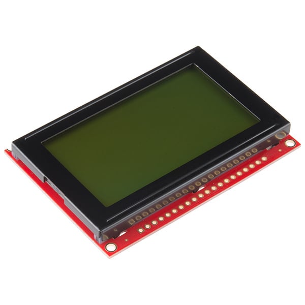
× 1GLCD 128x64 is a Graphical LCD having 128x64 pixel resolution. It is used to display values, text with different fonts, binary images, animation, custom character.
474-LCD-00710
Downloads
Comments43
Join the discussion — share a question or tip.
- AN
Hello. I'm trying to interface with ESP32 dev board using the U8g2 library. as I can see there is already this code part 'U8G2_KS0108_128X64_F'. Can you kindly suggest the pin connections I would need to make it work with ESP32? Code from in examples ... U8G2_KS0108_128X64_F u8g2(U8G2_R0, 8, 9, 10, 11, 4, 5, 6, 7, /*enable=*/ 18, /*dc=*/ 17, /*cs0=*/ 14, /*cs1=*/ 15, /*cs2=*/ U8X8_PIN_NONE, /* reset=*/ U8X8_PIN_NONE);
- DI
can we use custom font in this code?
- AU
I guess yes but might be limited
- HI
How to send a char received by usart to *char
- HI
Hello dear programmers help plz, my lcd 12864B V2.0 ST7920 has port PSB and NC instead of CS1 and CS2. I can not reproduce the text on the screen. Plz hel me to solve this problem.
- MA
Hi guys I want to start up a glcd by atmega128 in arduinoIDE How can I improve this program for my purpose? and what is a standard library for atmega128 in arduino IDE Thanks.
- MI
hello ,how to create image.h file that is included in the above program
- CH
sir i have code 128x64 glcd and my font 6x8 and i want print string page page0 and page1 middle how it is plz help 4 rows uper blank page0 and 4 rows down blank page1 plz reply both question
- CH
I have 16x4 lcd and i want reverse in string as for PD0-BD7 PD1-BD6 PD2-BD5 PD3-BD4 PD4-BD3 PD5-BD2 PD6-BD1 PD7 -BD0 have you got some idea sir if you know plz tell me
- CH
I tried so many time in atmega16
- AU
you mean making interface with joystick and print its position on glcd with symbol of write cursor ?
- CH
Replying to @authorized
Sir I want to cursor like as rectangle and moves up down using switch can you help me
- AUauthorized· edited
Replying to @chandannegich
ohhh, in that case you need to know below things =&gt; when to select CS1 and CS2 ( each half of display ). =&gt; when switch to next page =&gt; how to set cursor position with y address you need to track and update cursor position globally each time you press switch. i have not tried these things, but sure its possible. will try whenever i get time for it. if you get it work then let me know.
- CH
Hello sir how make Blvd cursor and how move 1 page to another page plz help
- CH
Glcd
- SH
hello sir , do you have the proteus library for Graphical LCD JHD12864E ??
- CO
Hello anybody can help me how to display number in glcd and select the spot like goto function
- AB
if i am using dfifferent data port like 6 data pin via portc and 7 and 8 data pin using port A and PORT B. how can use this pin beacause in my controller only some pin are free. sir please share the code.
- AB
how can i send the data in graphical lcd 128*64 interface with atmega32 controller using 4 datapin .
- AU
i am not sure but i think KS01088 glcd display driver does not support 4-bit mode.
- AB
Replying to @abhishekmishra
we are working on avr code vision if i am add the header file there are show display linking error. text image code is work but image.h file is not linking with compiler can you help me about this.
- AYayberkk· edited
Hi ,I have different combination for data and command ports on my board that I cannot change. Command port has seperate pins from A, B and D ports. How can I adapt the command port in your code ? Here is the image ->> https://i.hizliresim.com/Ay9EWB.png for my pin configuration. Thanks in advance
- LOlokeshc· edited
@ayberkk: hello friend, make below changes and check whether it is working for you or not. #define Data_Port_Dir DDRC #define RS_RW_Command_Port_Dir DDRA #define EN_RST_Command_Port_Dir DDRD #define Command_Port_Dir DDRB #define Data_Port PORTC #define RS_RW_Command_Port PORTA #define Command_Port PORTB #define EN_RST_Command_Port PORTD #define RS PA2 #define RW PA3 #define EN PD6 #define CS1 PB0 #define CS2 PB1 #define RST PD7 void GLCD_Command(char Command) /* GLCD command function */ { Data_Port = Command; /* Copy command on data pin */ RS_RW_Command_Port &= ~(1 << RS); /* Make RS LOW for command register*/ RS_RW_Command_Port &= ~(1 << RW); /* Make RW LOW for write operation */ EN_RST_Command_Port |= (1 << EN); /* Make HIGH-LOW transition on Enable */ _delay_us(5); EN_RST_Command_Port &= ~(1 << EN); _delay_us(5); } void GLCD_Data(char Data) /* GLCD data function */ { Data_Port = Data; /* Copy data on data pin */ RS_RW_Command_Port |= (1 << RS); /* Make RS HIGH for data register */ RS_RW_Command_Port &= ~(1 << RW); /* Make RW LOW for write operation */ EN_RST_Command_Port |= (1 << EN); /* Make HIGH-LOW transition on Enable */ _delay_us(5); EN_RST_Command_Port &= ~(1 << EN); _delay_us(5); } void GLCD_Init() /* GLCD initialize function */ { Data_Port_Dir = 0xFF; RS_RW_Command_Port_Dir |= (1 << RS)|(1 << RW); Command_Port_Dir |= (1 << CS1)|(1 << CS2); EN_RST_Command_Port_Dir |= (1 << EN)|(1 << RST); /* Select both left & right half of display & Keep reset pin high */ Command_Port |= (1 << CS1) | (1 << CS2); EN_RST_Command_Port |= (1 << RST); _delay_ms(20); GLCD_Command(0x3E); /* Display OFF */ GLCD_Command(0x40); /* Set Y address (column=0) */ GLCD_Command(0xB8); /* Set x address (page=0) */ GLCD_Command(0xC0); /* Set z address (start line=0) */ GLCD_Command(0x3F); /* Display ON */ }
- AY
Replying to @ayberkk
@ayberkk: Code is like this #define Data_Port_Dir DDRC #define RS_RW_Command_Port_Dir DDRA #define EN_RST_Command_Port_Dir DDRD #define Command_Port_Dir DDRB #define Data_Port PORTC #define RS_RW_Command_Port PORTA #define Command_Port PORTB #define EN_RST_Command_Port PORTD #define RS PA2 #define RW PA3 #define EN PD6 #define CS1 PB0 #define CS2 PB1 #define RST PD7 void GLCD_Command(char Command) /* GLCD command function */ { Data_Port = Command; /* Copy command on data pin */ RS_RW_Command_Port &= ~(1 << RS); /* Make RS LOW for command register*/ RS_RW_Command_Port &= ~(1 << RW); /* Make RW LOW for write operation */ EN_RST_Command_Port |= (1 << EN); /* Make HIGH-LOW transition on Enable */ _delay_us(5); EN_RST_Command_Port &= ~(1 << EN); _delay_us(5); } void GLCD_Data(char Data) /* GLCD data function */ { Data_Port = Data; /* Copy data on data pin */ RS_RW_Command_Port |= (1 << RS); /* Make RS HIGH for data register */ RS_RW_Command_Port &= ~(1 << RW); /* Make RW LOW for write operation */ EN_RST_Command_Port |= (1 << EN); /* Make HIGH-LOW transition on Enable */ _delay_us(5); EN_RST_Command_Port &= ~(1 << EN); _delay_us(5); } void GLCD_Init() /* GLCD initialize function */ { Data_Port_Dir = 0xFF; RS_RW_Command_Port_Dir |= (1 << RS)|(1 << RW); Command_Port_Dir |= (1 << CS1)|(1 << CS2); EN_RST_Command_Port_Dir |= (1 << EN)|(1 << RST); /* Select both left & right half of display & Keep reset pin high */ Command_Port |= (1 << CS1) | (1 << CS2); EN_RST_Command_Port |= (1 << RST); _delay_ms(20); GLCD_Command(0x3E); /* Display OFF */ GLCD_Command(0x40); /* Set Y address (column=0) */ GLCD_Command(0xB8); /* Set x address (page=0) */ GLCD_Command(0xC0); /* Set z address (start line=0) */ GLCD_Command(0x3F); /* Display ON */ } void GLCD_ClearAll() /* GLCD all display clear function */ { int i,j; /* Select both left & right half of display */ Command_Port |= (1 << CS1) | (1 << CS2); for(i = 0; i < TotalPage; i++) { GLCD_Command((0xB8) + i);/* Increment page */ for(j = 0; j < 64; j++) { GLCD_Data(0); /* Write zeros to all 64 column */ } } GLCD_Command(0x40); /* Set Y address (column=0) */ GLCD_Command(0xB8); /* Set x address (page=0) */ } void GLCD_String(const char* image) /* GLCD string write function */ { int column,page,page_add=0xB8,k=0; float page_inc=0.5; char byte; Command_Port |= (1 << CS1); /* Select Left half of display */ Command_Port &= ~(1 << CS2); for(page=0;page<16;page++) /* Print pages(8 page of each half)*/ { for(column=0;column<64;column++) { byte = pgm_read_byte(&image[k+column]); GLCD_Data(byte);/* Print 64 column of each page */ } Command_Port ^= (1 << CS1);/* Change segment controller */ Command_Port ^= (1 << CS2); GLCD_Command((page_add+page_inc));/* Increment page address*/ page_inc=page_inc+0.5; k=k+64; /* Increment pointer */ } GLCD_Command(0x40); /* Set Y address (column=0) */ GLCD_Command(0xB8); /* Set x address (page=0) */ } int main(void) { GLCD_Init(); /* Initialize GLCD */ GLCD_ClearAll(); /* Clear all GLCD display */ GLCD_String(img); /* Print Image Array */ while(1); }
- YAyash· edited
Hello, I tried this tutorial with Atmega328, I am not getting the output as expected. There is a problem in right half of display...like if on line of right half 'Hello' is displayed then on second line 'Hello' will start below after where 'Hello' on first line ended. e.g Hello Hello Here is the image I uploaded on imgur-> https://imgur.com/a/jcdGs please help or suggest something
- LO
@yash: Hello friend, the above code is tested on atmega16 & GLCD jhd12864e and it is working fine for me. As per your query I tested the same code on atmega328 and i get the same result as expected. I also find your link and tested your words in image. but nothing goes wrong, I got the expected output which I have posted here ->https://imgur.com/a/Qi0uH I just used the PORTD instead of port (PORTA) used in above code. check your GLCD display module is the same as I mentioned above i.e. GLCD jhd12864e
- YAyash· edited
Replying to @lokeshc
@lokeshc: Oh ok, I used PortC for commands and PortD for data. here is the code I modified as per Atmega328. (Please check the code, I also tried playing around with code to check if anything helps out but it didn't so some part of code might be wrong as I don't remember if I reverted the code back to original) #define F_CPU 16000000L #include <avr/io.h> #include <util/delay.h> #include <stdio.h> #include "Font_Header.h" #define DataP PORTD #define CommP PORTC #define DataPReg DDRD #define CommPReg DDRC #define RS PC0 #define RW PC1 #define EN PC2 #define CS1 PC3 #define CS2 PC4 #define RST PC5 #define totalPage 8 void glcdcomm(char command) { DataP = command; CommP &= ~(1<<RS); CommP &= ~(1<<RW); CommP |= (1<<EN); _delay_us(5); CommP &= ~(1<<EN); _delay_us(5); } void glcddata(char data) { DataP = data; CommP |= (1<<RS); CommP &= ~(1<<RW); CommP |= (1<<EN); _delay_us(5); CommP &= ~(1<<EN); _delay_us(5); } void glcdinit() { DataPReg = 0xFF; CommPReg = 0xFF; CommP |= (1<<CS1)|(1<<CS2)|(1<<RST); _delay_ms(20); glcdcomm(0x3E); glcdcomm(0x40); glcdcomm(0xB8); glcdcomm(0xC0); glcdcomm(0x3F); } void glcdclr() { int i,j; CommP|=(1<<CS1)|(1<<CS2); for(i=0; i<totalPage; i++) { glcdcomm((0xB8)+i); for(j = 0; j<64; j++) { glcddata(0); } } glcdcomm(0x40); glcdcomm(0xB8); } void glcdstring(char pgno, char *str) { unsigned int i, col; unsigned int pg = ((0xB8)+pgno); unsigned int Yadd = 0; float pginc = 0.5; CommP |= (1<<CS1); CommP &= ~(1<<CS2); glcdcomm(pg); for (i=0;str[i] != 0;i++) { if (Yadd > (1024-(((pgno)*128)+FontWidth))) break; if (str[i]!=32) { for (col=1; col<=FontWidth; col++) { if ((Yadd+col)==(128*((int)(pginc+0.5)))) { if (col == FontWidth) break; glcdcomm(0x40); Yadd = Yadd + col; CommP ^= (1 << CS1); CommP ^= (1 << CS2); glcdcomm(pg + pginc); pginc = pginc + 0.5; } } } if (Yadd>(1024-(((pgno)*128)+FontWidth))) break; if((font[((str[i]-32)*FontWidth)+4])==0 || str[i]==32) { for(col=0; col<FontWidth; col++) { glcddata(font[str[i]-32][col]); if((Yadd+1)%64==0) { CommP ^= (1 << CS1); CommP ^= (1 << CS2); glcdcomm((pg+pginc)); pginc = pginc + 0.5; } Yadd++; } } else { for(col=0; col<FontWidth; col++) { glcddata(font[str[i]-32][col]); if((Yadd+1)%64==0) { CommP ^= (1 << CS1); CommP ^= (1 << CS2); glcdcomm((pg+pginc)); pginc = pginc + 0.5; } Yadd++; } glcddata(0); Yadd++; if((Yadd)%64 == 0) { CommP ^= (1 << CS1); CommP ^= (1 << CS2); glcdcomm((pg+pginc)); pginc = pginc + 0.5; } } } } int main(void) { glcdinit(); glcdclr(); glcdclr(); glcdstring(1,"NMT CNC GUI Axis"); glcdstring(2,"NMT CNC GUI Axis"); glcdstring(3,"NMT CNC GUI Axis"); glcdstring(4,"NMT CNC GUI Axis"); while(1); }
- LO
Replying to @yash
@yash: Hi Yash, In glcdstring() function, you have not set the Y-address. Because of this, it may display a string on the unexpected position of the display. Specify the Y-address at last in glcdstring() function and then test it again. Maybe your problem will solve and let me know if a problem is not solved. Also, please confirm your GLCD model (here JHD12864e).
- LO
Replying to @yash
@yash: Hello yash, i used the same above example program for atmega328. only i changed the PORTA to PORTD and it working fine for me. i did not understand what is erratic in it. I will suggest you to make sure your pin connections are not loose. also make sure you are not using that pins for another multiple functions like ADC or Serial uart if still its not works share your glcd display snap as before you did.