DHT11 Sensor Interfacing with AVR ATmega16/ATmega32.
Interface single wire DHT11 sensor with ATmega16/ATmega32 and read the value of Temperature and Humidity from DHT11. Display these Temperature and Humidity values on a 16x2 LCD.
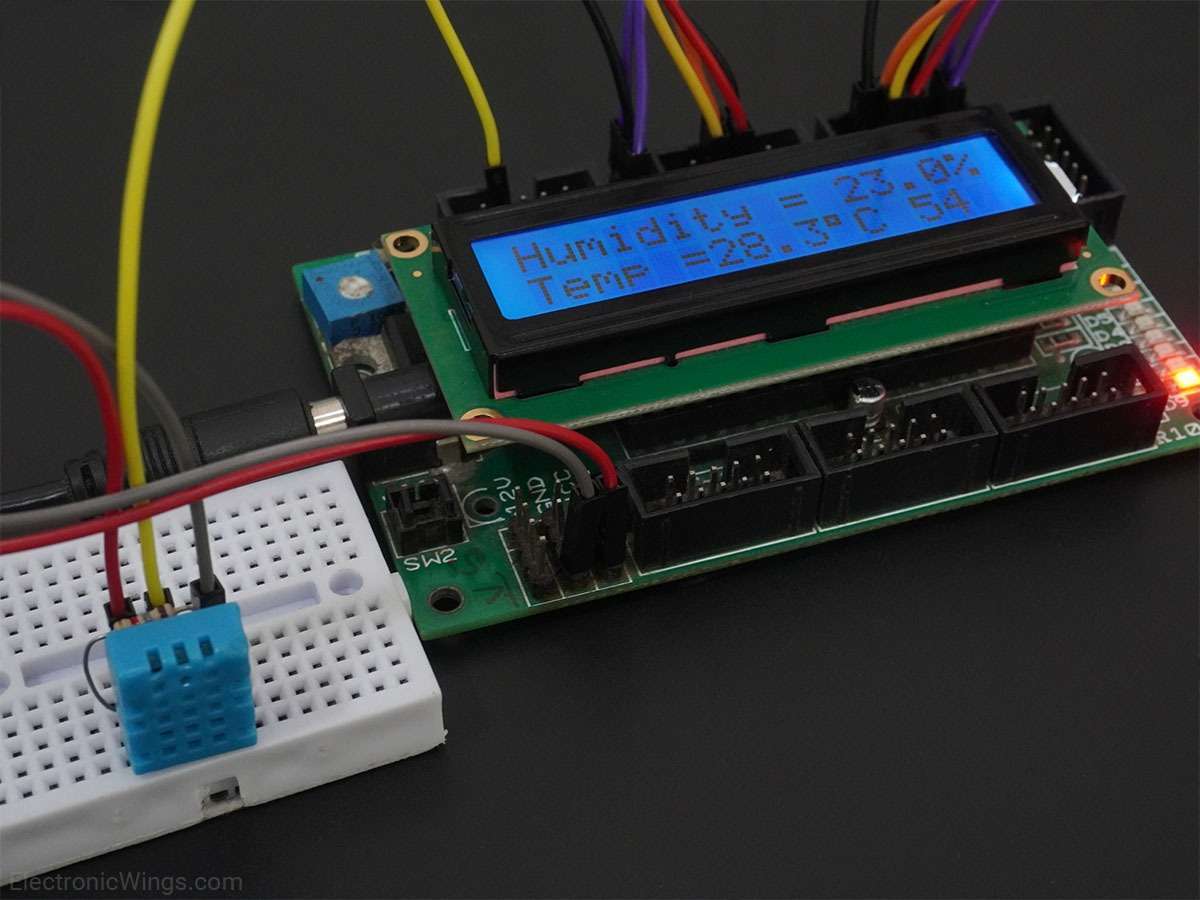
Overview of DHT11
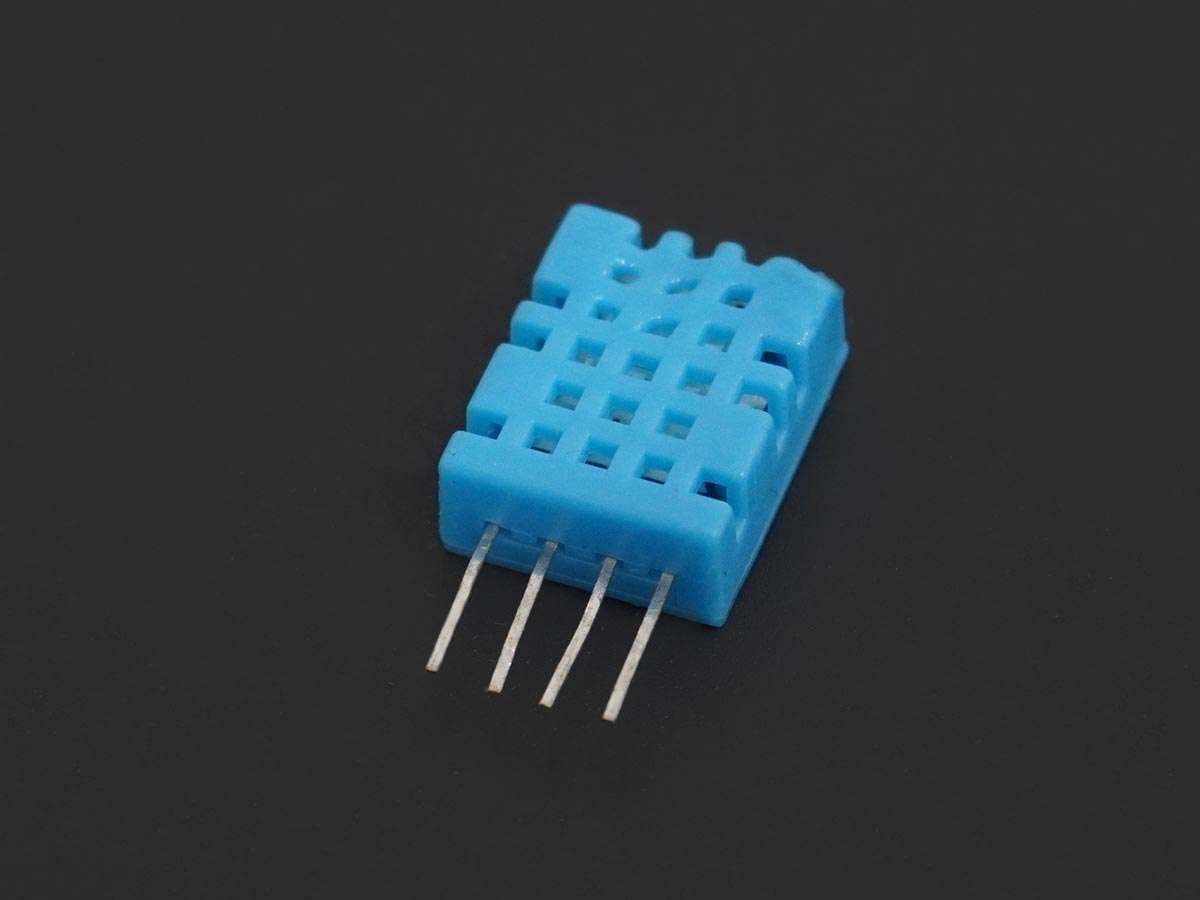
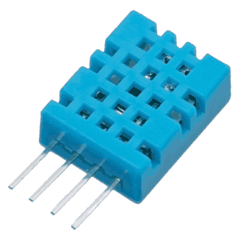
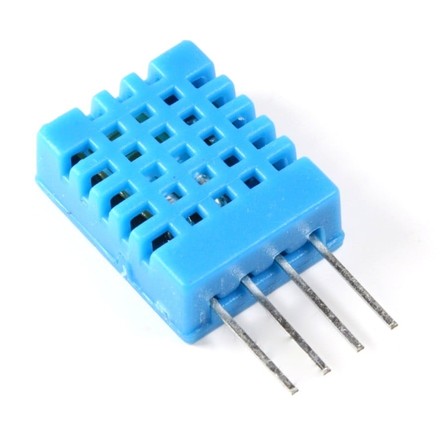
DHT11 is a single wire digital humidity and temperature sensor, which provides humidity and temperature values serially.
It can measure the relative humidity in percentage (20 to 90% RH) and temperature in degree Celsius in the range of 0 to 50°C.
It has 4 pins of which 2 pins are used for supply, 1 is not used and the last one is used for data.
The data is the only pin used for communication. Pulses of different TON and TOFF are decoded as logic 1 or logic 0 or start pulse or end of the frame.
For more information about the DHT11 sensor and how to use it, refer to the topic DHT11 sensor in the sensors and modules topic.
Connection Diagram of DHT11 with ATmega16/32
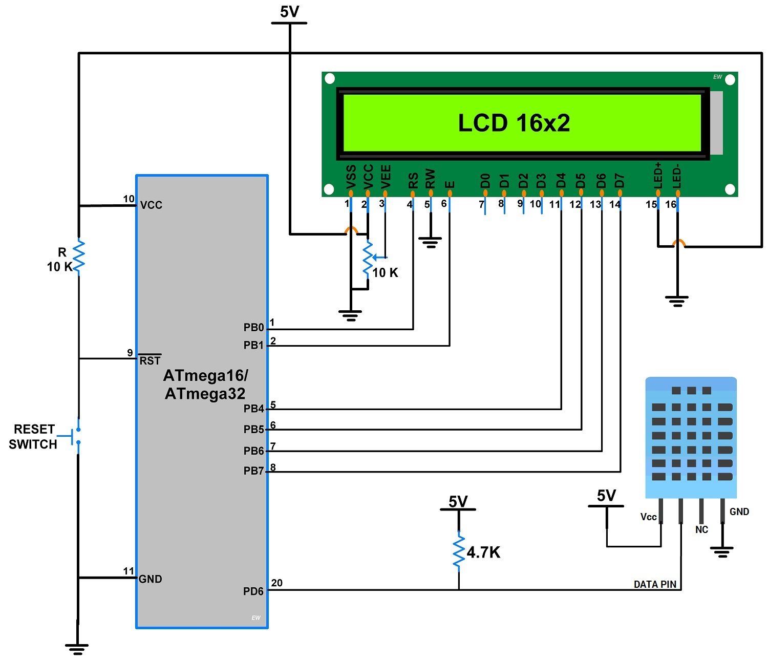
- The above circuit diagram shows the interfacing of AVR ATmega16/ATmega32 to the DHT11 sensor.
In that, LCD is interfaced to PORTB in 4-bit mode, and a DHT11 sensor is connected to PD6 (Pin no 20).
DHT11 Code for ATmega16/32
- First, initialize the LCD16x2_4bit library.
- Define pin no. to interface DHT11 sensor, in our program we define PD6 (Pin no. 20).
- Send the start pulse to the DHT11 sensor, making low to high.
- Receive the response pulse from the DHT11 sensor.
- After receiving the response, receive 40-bit data serially from the DHT11 sensor.
- Display this received data on LCD16x2 along with error indication.
Code
/*
 * ATmega16_DHT11_Project_File.c
 *
 * http://www.electronicwings.com
 */

#include <avr/io.h>
#include <stdlib.h>
#include <stdio.h>
#include "LCD16x2_4bit.h"
#define DHT11_PIN 6
uint8_t c=0,I_RH,D_RH,I_Temp,D_Temp,CheckSum;

void Request()				/* Microcontroller send start pulse/request */
{
	DDRD |= (1<<DHT11_PIN);
	PORTD &= ~(1<<DHT11_PIN);	/* set to low pin */
	_delay_ms(20);			/* wait for 20ms */
	PORTD |= (1<<DHT11_PIN);	/* set to high pin */
}

void Response()				/* receive response from DHT11 */
{
	DDRD &= ~(1<<DHT11_PIN);
	while(PIND & (1<<DHT11_PIN));
	while((PIND & (1<<DHT11_PIN))==0);
	while(PIND & (1<<DHT11_PIN));
}

uint8_t Receive_data()			/* receive data */
{
	for (int q=0; q<8; q++)
	{
		while((PIND & (1<<DHT11_PIN)) == 0);  /* check received bit 0 or 1 */
		_delay_us(30);
		if(PIND & (1<<DHT11_PIN))/* if high pulse is greater than 30ms */
		c = (c<<1)|(0x01);	/* then its logic HIGH */
		else			/* otherwise its logic LOW */
		c = (c<<1);
		while(PIND & (1<<DHT11_PIN));
	}
	return c;
}

int main(void)
{
	char data[5];
	lcdinit();			/* Initialize LCD */
	lcd_clear();			/* Clear LCD */
	lcd_gotoxy(0,0);		/* Enter column and row position */
	lcd_print("Humidity =");
	lcd_gotoxy(0,1);
	lcd_print("Temp = ");

    while(1)
	{
		Request();		/* send start pulse */
		Response();		/* receive response */
		I_RH=Receive_data();	/* store first eight bit in I_RH */
		D_RH=Receive_data();	/* store next eight bit in D_RH */
		I_Temp=Receive_data();	/* store next eight bit in I_Temp */
		D_Temp=Receive_data();	/* store next eight bit in D_Temp */
		CheckSum=Receive_data();/* store next eight bit in CheckSum */

		if ((I_RH + D_RH + I_Temp + D_Temp) != CheckSum)
		{
			lcd_gotoxy(0,0);
			lcd_print("Error");
		}

		else
		{
			itoa(I_RH,data,10);
			lcd_gotoxy(11,0);
			lcd_print(data);
			lcd_print(".");

			itoa(D_RH,data,10);
			lcd_print(data);
			lcd_print("%");

			itoa(I_Temp,data,10);
			lcd_gotoxy(6,1);
			lcd_print(data);
			lcd_print(".");

			itoa(D_Temp,data,10);
			lcd_print(data);
			lcddata(0xDF);
			lcd_print("C ");

			itoa(CheckSum,data,10);
			lcd_print(data);
			lcd_print(" ");
		}

	_delay_ms(10);
	}
}
Video of Measuring Temperature and Humidity using DHT11 and Atmega16/32
Components Used
Powered by
 × 1
× 1DHT11 is a single wire digital humidity and temperature sensor, which gives relative humidity in percentage and temperature in degree Celsius.
485-386
Downloads
Comments51
Join the discussion — share a question or tip.
- FA
Why doesn't this program work with atmega328?! I tested this program with atmega8,16 and it worked fine but with Atmega328 it doesn't show the temperature and humidity at all
- JA
I am getting errors about lcddata, lcdinit and all other those kind of instructions please someone help
- SA
hello, convert _delay_ms(10); to _delay_ms(2000);
- IM
Nice guide, thanks, man. I changed it to run on Atmega328p via UART. I'll leave a link when I upload the code.
- IM
here you go https://github.com/ImpulseImp/My_libs/blob/main/DHT11/main.c
- SA
Hi, I am also trying this and if you are not able to run this program, go to cksel==internal 8mhz. Believe me its working. Works for atmega16. Good luck!! keep learning.
- EM
I have a problem where, when i connect as viewed on the circuit diagram, i get and "error" where nothing is displayed on the LCD, but the first row of of pixels is on and the second is off? is there anyone who has the same problem? or knows what to do?
- BE
hello what is the function of the c variable? please help me
- UL
"cheers love, the cavalry's here." Response() is main villain. Solution is here. 1. replace response function int Response() { DDRD &= ~(1<<DHT11_PIN); _delay_us(39); if((PIND & (1<<DHT11_PIN))) //response signal error check! return 1; _delay_us(80); if(!(PIND & (1<<DHT11_PIN))) //pulled ready output check! return 1; _delay_us(80); } 2. add signal error check 'if' Request(); /* send start pulse */ if(Response() != 1) /* receive response */ { I_RH = Receive_data(); /* store first eight bit in I_RH */ D_RH = Receive_data(); /* store next eight bit in D_RH */ I_Temp = Receive_data(); /* store next eight bit in I_Temp */ D_Temp = Receive_data(); /* store next eight bit in D_Temp */ CheckSum = Receive_data();/* store next eight bit in CheckSum */ } 3. good luck
- RI
Replying to @lmike2018
Hi, i´m having the exactly same problem, did you solve it?
- 97
I change this code and use it in Atmega 328p, there aren't any mistakes in code but it still can not readout value. could u plz give me some supports? here is the code #define D4 eS_PORTD4 #define D5 eS_PORTD5 #define D6 eS_PORTD6 #define D7 eS_PORTD7 #define RS eS_PORTB0 #define EN eS_PORTB1 #define F_CPU 16000000UL #define BAUDRATE 9600 #define BAUD_PRESCALLER (((16000000UL / (BAUDRATE * 16UL))) - 1) #include <avr/io.h> #include <stdlib.h> #include "lcd.h" #include <util/delay.h> #include <string.h> #define DHT11_PIN PINC0 uint8_t c=0,I_RH,D_RH,I_Temp,D_Temp,CheckSum; void DHT11_initial() /* Microcontroller send start pulse/request */ { DDRC |= (1<<DHT11_PIN); PORTC |= (1<<DHT11_PIN); /* add this line */ _delay_ms(100); /* add this line */ PORTC &= ~(1<<DHT11_PIN); /* set to low pin */ _delay_ms(100); /* wait for 100ms */ PORTC |= (1<<DHT11_PIN); /* set to high pin */ } void DHT11_Response() /* receive response from DHT11 */ { DDRC &= ~(1<<DHT11_PIN); while(PINC & (1<<DHT11_PIN)); while((PINC & (1<<DHT11_PIN))==0); while(PINC & (1<<DHT11_PIN)); } uint8_t Receive_data() /* receive data */ { for (int q=0; q<8; q++) { while(!(PINC & (1<<DHT11_PIN))); /* check received bit 0 or 1 */ _delay_us(30); if(PINC & (1<<DHT11_PIN))/* if high pulse is greater than 30ms */ c = (c<<1)|(0x01); /* then its logic HIGH */ else /* otherwise its logic LOW */ c = (c<<1); while(PINC & (1<<DHT11_PIN)); } return c; } int main(void) { DDRD=0xFF; DDRB=0xFF; char data[5]; Lcd4_Clear(); /* Clear LCD */ Lcd4_Init(); /* Initialize LCD */ Lcd4_Set_Cursor(1,0); /* Enter row and column position */ Lcd4_Write_String("Humi="); Lcd4_Set_Cursor(2,0); Lcd4_Write_String("Temp="); while(1) { DHT11_initial(); /* send start pulse */ DHT11_Response(); /* receive response */ I_RH=Receive_data(); /* store first eight bit in I_RH */ D_RH=Receive_data(); /* store next eight bit in D_RH */ I_Temp=Receive_data(); /* store next eight bit in I_Temp */ D_Temp=Receive_data(); /* store next eight bit in D_Temp */ CheckSum=Receive_data();/* store next eight bit in CheckSum */ if ((I_RH + D_RH + I_Temp + D_Temp) != CheckSum) { Lcd4_Set_Cursor(1,1); Lcd4_Write_String("Error"); } else { itoa(I_RH,data,10); Lcd4_Set_Cursor(1,6); Lcd4_Write_String(data); Lcd4_Write_String("."); itoa(D_RH,data,10); Lcd4_Write_String(data); Lcd4_Write_String("%"); itoa(I_Temp,data,10); Lcd4_Set_Cursor(2,6); Lcd4_Write_String(data); Lcd4_Write_String("."); itoa(D_Temp,data,10); Lcd4_Write_String(data); Lcd4_Write_String("C "); } _delay_ms(10); } }
- HE
Did you ever get this working on the ATmega328p? Because I am also trying to adapt the original code to this microcontroller
- LB
Hi! Is this topic stil alive? I have problem with this code. The readings are fine, but the readings go for only two or three loops, and than it stops. Because your code is a part of a loop, when your code stops, it doesn't allow for the rest of the loop to continue. How to solve this? Thank you!
- HE
please need help
- HE
i realized that the DHT22 never respond it always see High so it get stuck in the first wile of the response function? any help please ?
- HE
i have write this code typically and it get stuck in response function and when i delete the lines that get stucked on it the sensor always reading logic 1
- NI
The while loop is not working for me. It is getting stuck on Request() function.
- NInikhil77nik· edited
Replying to @lokeshc
Yes. You are right. Its Response(). But connections are right. What else could be the problem?
- NI
Replying to @lokeshc
I have a DHT11 module which doesn't require a pull-up resistor. I have even changed fuse bits of Atmega16 to 8 kHz. Still, the problem is being there.
- LO
Replying to @nikhil77nik
Test code by replacing Request() function using below code, void Request() /* Microcontroller send start pulse/request */ { DDRD |= (1<<DHT11_PIN); PORTD &= ~(1<<DHT11_PIN); /* set to low pin */ _delay_ms(18); /* wait for 20ms */ PORTD |= (1<<DHT11_PIN); /* set to high pin */ _delay_ms(20); /* wait for 20ms */ }
- YV
Intéressant!pour moi un soucis avec atmel studio 7 Erreur conflicting types for 'Receive_data' uint8_t Receive_data() { for (int q=0; q<8; q++) { while((PIND & (1<<DHT11_PIN)) == 0); _delay_us(30); if(PIND & (1<<DHT11_PIN)) c = (c<<1)|(0x01); else c = (c<<1); while(PIND & (1<<DHT11_PIN)); } return c; }
- YV
Merci de la réponce! pour aller un peu plus loin voici la portion de code ou est exploité la fonction receive_data() I_RH = Receive_data(); /* store first eight bit in I_RH */ D_RH=Receive_data(); /* store next eight bit in D_RH */ I_Temp=Receive_data(); /* store next eight bit in I_Temp */ D_Temp=Receive_data(); /* store next eight bit in D_Temp */ CheckSum=Receive_data();/* store next eight bit in CheckSum */ if ((I_RH + D_RH + I_Temp + D_Temp) != CheckSum) { Lcd4_Set_Cursor(0,0); Lcd4_Write_String("Error"); } else { itoa(I_RH,data,10); Lcd4_Set_Cursor(11,0); Lcd4_Write_String(data); Lcd4_Write_String("."); itoa(D_RH,data,10); Lcd4_Write_String(data); Lcd4_Write_String("%"); itoa(I_Temp,data,10); Lcd4_Set_Cursor(6,1); Lcd4_Write_String(data); Lcd4_Write_String("."); itoa(D_Temp,data,10); Lcd4_Write_String(data); lcddata(0xDF); Lcd4_Write_String("C "); itoa(CheckSum,data,10); Lcd4_Write_String(data); Lcd4_Write_String(" "); }
- HU
It was not working for me, it was only reading 4 or 5 times and after that stucks. My solution was to add two lines to the Request function: void Request() /* Microcontroller send start pulse/request */ { DDRD |= (1<<DHT11_PIN); PORTD |= (1<<DHT11_PIN); /* add this line */ _delay_ms(100); /* add this line */ PORTD &= ~(1<<DHT11_PIN); /* set to low pin */ _delay_ms(20); /* wait for 20ms */ PORTD |= (1<<DHT11_PIN); /* set to high pin */ }
- RA
Sir in this program while(1) is not working means it display humidity and temp for only one time...
- HEhetupatel11h2· edited
@rajeevsharma2482: 1)before while loop,put a delay of 100ms and 2)change last delay of 10ms..put delay of 500ms instead of that.. i m using 16mhz crystal...for my board.. hope it will work ;)