Timer Input Capture Mode in AVR ATmega16/ATmega32
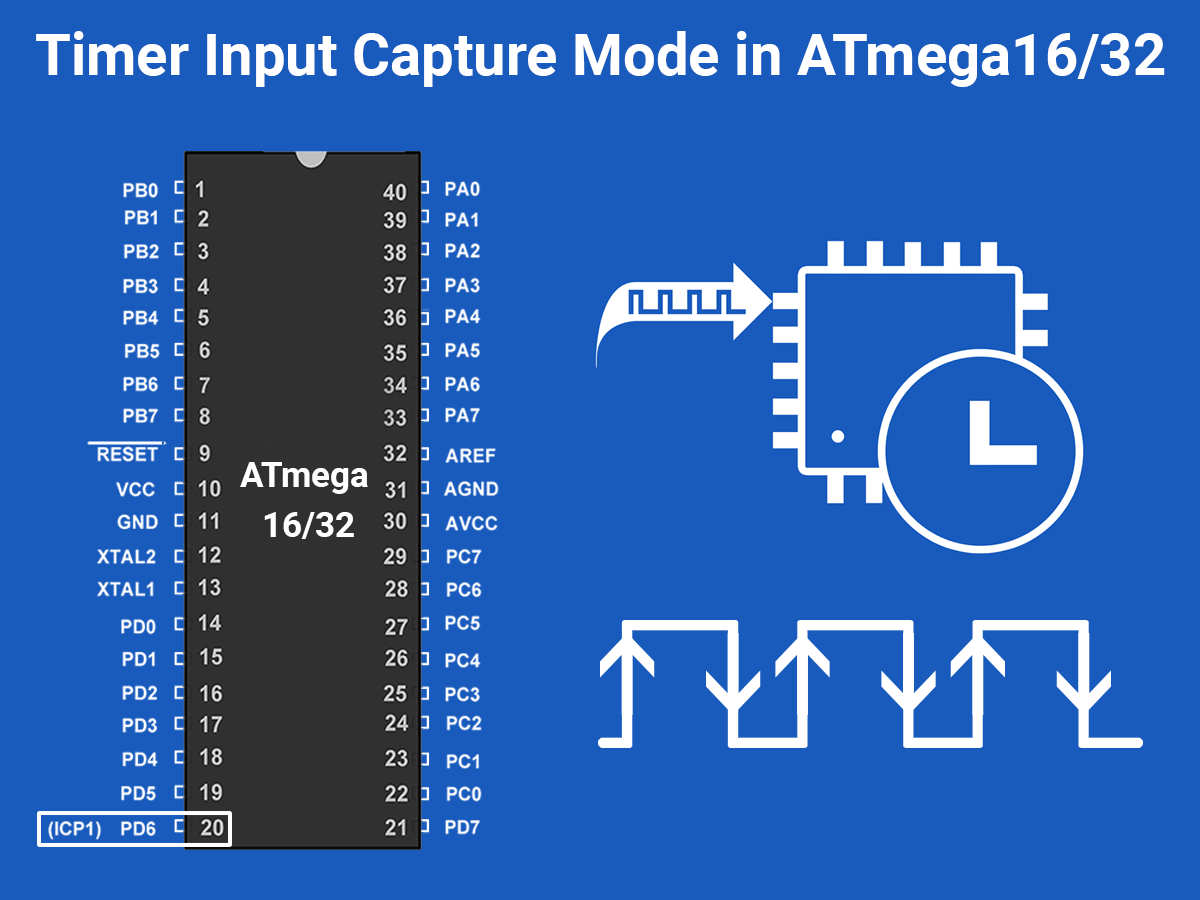
AVR Atmega16/ATmega32 has a feature of Input Capture Mode through which it can capture signal rising or falling edge events on its pin.
Introduction to Input Capture Mode
The input capture function is used in many applications such as:
- Pulse width measurement
- Period measurement
- Capturing the time of an event
In AVR ATmega32, Timer1 can be used as an input capture to detect and measure events happening outside the microcontroller.
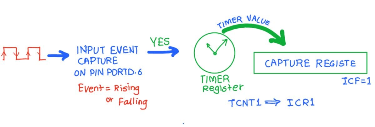
Upon detection of a defined event i.e. rising edge or falling edge on ICP pin (PORTD.6), the TCNT1(Timer / Counter register) value is loaded into the ICR1 (input capture) register and the ICF1 flag will get set.
Programming ICP Registers
To program, first, let us see TCCR1B (Timer Counter Control Register B)
TCCR1B: Timer Counter Control Register B

Bit 7 - ICNC1: Input Capture Noise canceller
Setting this bit activates the noise canceller. It causes a delay of 4 clock cycles as it considers a change only if it persists for at least 4 successive system clocks.
Bit 6 - ICES1: Input Capture Edge select
Select edge detection for input capture function.
0 = Capture on the falling edge
1 = Capture on rising edge
Bit 4: 3 - WGM13 : WGM12: Timer1 Mode select
These bits are used for mode selection like Normal mode, PWM mode, CTC mode, etc. here we will select normal mode, so set these bits to zero.
Bit 2: 0 - CS12: CS10:Timer1 Clock Select
| CS02 | CS01 | CS00 | Description |
|---|---|---|---|
| 0 | 0 | 0 | No clock source (Timer / Counter stopped) |
| 0 | 0 | 1 | clk (no pre-scaling) |
| 0 | 1 | 0 | clk / 8 |
| 0 | 1 | 1 | clk / 64 |
| 1 | 0 | 0 | clk / 256 |
| 1 | 0 | 1 | clk / 1024 |
| 1 | 1 | 0 | External clock source on T0 pin. Clock on falling edge |
| 1 | 1 | 1 | External clock source on T0 pin. Clock on rising edge. |
Steps to Program
- Initialize the TCCR1A and TCCR1B for proper timer mode (any mode other than 8, 10, 12, 14), to select the edge (Positive or Negative).
- Monitor the ICF1 flag in the TIFR register to see if the edge has arrived. Upon the arrival of the edge, the TCNT1 value is loaded into the ICR1 register automatically by the controller.
Note: Input capture pin, which is PORTD.6, has one more function i.e. output of the analog comparator. We can use ACIC bit from the ACSR register, to make this pin function as the ‘analog comparator output’ by setting it to logic HIGH. Otherwise, this pin remains as an ICP pin by default after power on or reset. So we don’t need to define this Register here.
Input Capture Mode Program
Assuming that the clock pulses are fed into the pin ICP1, the following program will read the TCNT1 value at every rising edge and place the result on PORTA and PORTB.
/*
 ATmega16 input capture mode
 http://www.electronicwings.com
 */

#include "avr/io.h"
int main ( )
{
	unsigned int t;
	DDRA = 0xFF;
	DDRB = 0xFF;
	PORTD = 0xFF;
	TCCR1A = 0;
	TIFR = (1<<ICF1);		/* clear input capture flag */
	TCCR1B = 0x41;			/* capture on rising edge */

	while ((TIFR&(1<<ICF1)) == 0);  /* monitor for capture*/
	t = ICR1;
	TIFR = (1<<ICF1);		/* clear capture flag */

	while ((TIFR&(1<<ICF1)) == 0);  /* monitor for next rising
					edge capture */

	t = ICR1 - t;  			/* period= recent capture-
					previous capture */
	PORTA = t;  			/* put period count on PORTA & PORTB */
	PORTB = t>>8;

	while (1);
	return 0;
}
Measuring Frequency and Duty Cycle
Program to measure the frequency and duty cycle and displaying it on the LCD16x2
/*
  Measuring ATmega16 frequency and duty cycle using input capture
  http://www.electronicwings.com
 */


#define F_CPU 8000000UL
#include <avr/io.h>
#include <util/delay.h>
#include <avr/interrupt.h>
#include <stdlib.h>
#include "LCD_16x2_H_file.h"

int main ( )
{
	unsigned int a,b,c,high,period;
	char frequency[14],duty_cy[7];

	LCD_Init();
	PORTD = 0xFF;			/* Turn ON pull-up resistor */

	while(1)
	{
		TCCR1A = 0;
		TCNT1=0;
		TIFR = (1<<ICF1);  	/* Clear ICF (Input Capture flag) flag */

		TCCR1B = 0x41;  	/* Rising edge, no prescaler */
		while ((TIFR&(1<<ICF1)) == 0);
		a = ICR1;  		/* Take value of capture register */
		TIFR = (1<<ICF1);  	/* Clear ICF flag */

		TCCR1B = 0x01;  	/* Falling edge, no prescaler */
		while ((TIFR&(1<<ICF1)) == 0);
		b = ICR1;  		/* Take value of capture register */
		TIFR = (1<<ICF1);  	/* Clear ICF flag */

		TCCR1B = 0x41;  	/* Rising edge, no prescaler */
		while ((TIFR&(1<<ICF1)) == 0);
		c = ICR1;  		/* Take value of capture register */
		TIFR = (1<<ICF1);  	/* Clear ICF flag */

		TCCR1B = 0;  		/* Stop the timer */

		if(a<b && b<c)  	/* Check for valid condition,
					to avoid timer overflow reading */
		{
			high=b-a;
			period=c-a;

			long freq= F_CPU/period;/* Calculate frequency */

						/* Calculate duty cycle */
            		float duty_cycle =((float) high /(float)period)*100;
			ltoa(freq,frequency,10);

			itoa((int)duty_cycle,duty_cy,10);

			LCD_Command(0x80);
			LCD_String("Freq: ");
			LCD_String(frequency);
			LCD_String(" Hz    ");

			LCD_Command(0xC0);
			LCD_String("Duty: ");
			LCD_String(duty_cy);
			LCD_String(" %      ");

		}

		else
		{
			LCD_Clear();
			LCD_String("OUT OF RANGE!!");
		}
		_delay_ms(50);
	}

}
Video
Components Used
Powered by
Downloads
Comments25
Join the discussion — share a question or tip.
- ES
Working with very precise readings , But when disconnect the input captured signal, The whole program stop ,stucked in the while waiting the Flag to be set , How to avoid program stuck waiting for input capture flag
- LE
Como se conecta el lcd?
- MU
we haven't considered the overflow in TCNT1. I think we have to consider that for a generalized input capture
- AM
need an explantion for this code :long freq= F_CPU/period; ?? why do we divide th frquency by the calculated period
- MU
because period = c-a is not actual period. Since TCNT1 register doesn't increment one bit at a second. it increment at the clock rate. so you have to take that into consideration. some logical thinking will sort that out.
- AM
what is the maning of this line PORTB = t>>8;?
- MU
using PORTA we get the LS bits of time and using PORTB we get the MSBits of the time. so in order fill only the MSBs into port B we need to shift the values by 8 bits
- AM
why do define PORTD in the first code as high ?
- MO
to use the pull up resistor ... to use this pin "portD.6" as I/P ... to detect rising or falling edge of the input signal ..
- TR
Can you do this using ICP3?. Because there are some difference between Timer1 and Timer3.
- PU
how to use for 16 MHz freq. ?
- KA
could you please tell me that if you've found the method
- PU
Can i use this program in ATmega328P Controller ?
- ME
Thank you!! Perfect guide. Freq and duty measurement code working very well for 50 Hz.
- WI
Thank you for explanation, i want ask you why the register TICIE1 is not set??