OLED Graphic Display Interfacing With Arduino UNO
OLED graphic display modules are compact and have high contrast pixels which make these displays easily readable. They do not require backlight since the display creates its own light. Hence they consume less power. Both I2C and SPI based OLED modules are available in market
Overview of SSD1306 OLED Module
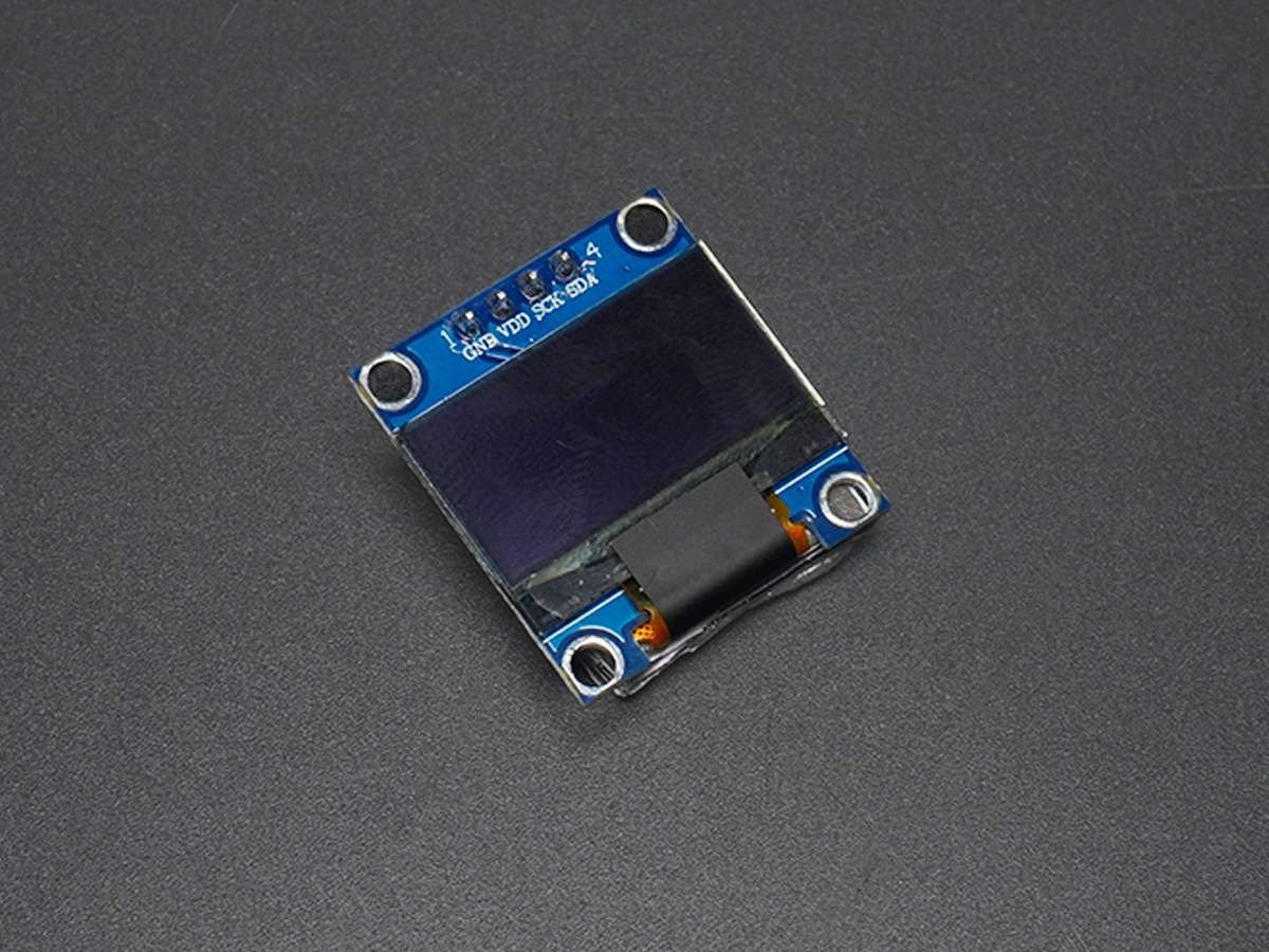
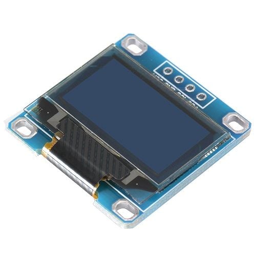
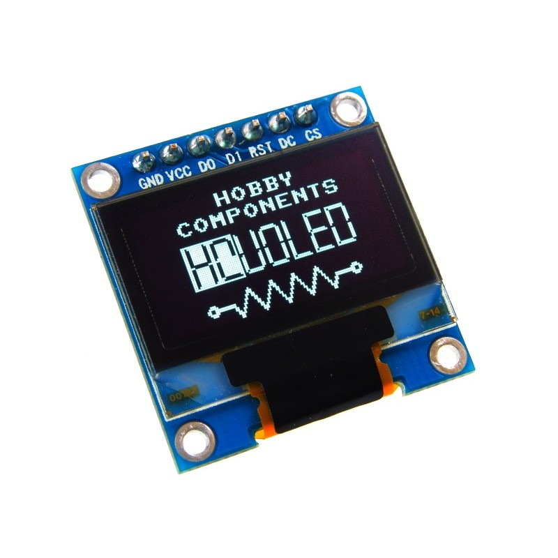
The OLED module shown in the above image is a very popular module available in the market.
There are many variants of this module available in the market, having different resolutions, communication protocols, or pixel colors.
These OLED modules are driven by SSD1306 IC which is a driver IC for 128x64 Dot Matrix OLED segments. The SSD1306 has its own controller and supports both SPI and I2C communication protocols. Hence, there are various OLED modules in the market, some that support only SPI communication, some that support only I2C communication, and some that support both I2C and SPI communication. (Different number of pins for different modules)
Since the driver IC supports 128x64 resolution, there are some variants that have a lesser resolution like 128x32.
Different modules support different colors like blue, yellow, and white. Some modules support multiple colors as well. You will need to check the specifications of your display module to know which colors are supported.
We are using a 4-pin I2C supported 128x64 OLED module similar to the one shown in the above image.
For more information about OLED and how to use it, refer the topic SSD1306 OLED Display in the sensors and modules section.
OLED 128x64 Pinout
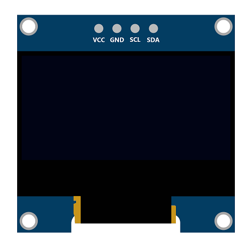
OLED 128x64 Pin Description
The above image shows a 128x64 I2C based OLED module.
VCC: This is the power pin for the module. A supply of 3.3V or 5V can be provided to this pin to power the display.
GND: This is the ground pin for the module.
SCL and SDA: These are the serial clock and serial data pins for I2C communication.
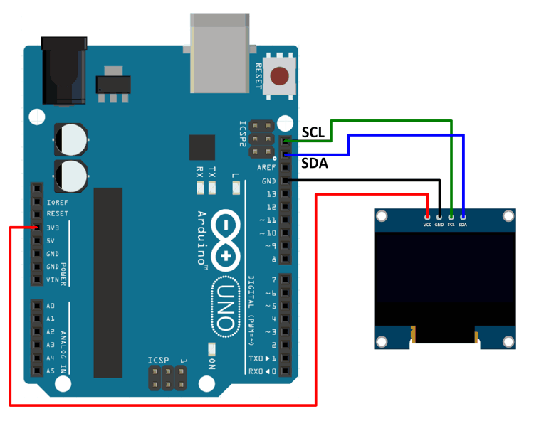
Connection Diagram of 0.96" OLED 128x64 with Arduino
Display Text, Images, and Patterns on a 128x64 OLED module using Arduino Uno
Here, we are using Adafruit’s library for SSD1306. This library is available on GitHub.
Download this library from here.
This library is for monochrome displays only.
We will need the Adafruit GFX library as well for the patterns, images, and text that we will be displaying on the display.
Download this library from here.
Extract these libraries and add them to the libraries folder path of Arduino IDE.
For information about how to add a custom library to the Arduino IDE and use examples from it, refer Adding Library To Arduino IDE in the Basics section.
The Adafruit library for SSD1306 comes with 4 example sketches by Adafruit. You can directly upload one of the sketches (depending on your device and the communication protocol supported) to your device.
Here we have created an example sketch of our own, based on the functions defined in the two libraries.
Note : Ensure that you use the appropriate I2C device address. Device address used is either 0x3C or 0x3D. Use one of these addresses. You will have to find out which one is your device’s address. This address is not the 8-bit device address; it is the address that is formed by the 7-bits without considering the read or write bit. Try one of these addresses, if it does not work, use the other.
Note : The drawBitmap function from the Adafruit_GFX library that is used for drawing images requires a peculiar array of the image.
For OLED display (128x64), the array should contain image data scanned as 128 pixels per row and 64 such rows, starting from the origin of the image. Each element in the array (the array is a character array) contains information about 8 consecutive pixels. If we start at the origin, the first 16 elements (8 bits/element, 16*8=128) in the array will contain the information about the 128 pixels in the 1st row (1 is a pixel on, 0 is a pixel off). The next 16 elements will have information about the 128 pixels in the 2nd row and so on.
The data in the image array can be in hex form or binary form or decimal form.
Example: Consider that the first element in the image array is 0x0F (or 15 or 0B00001111)
In this case, the first 4 pixels in the first row will be off. The 5th, 6th, 7th, and 8th pixels will be on.
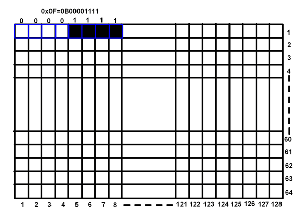
Word of Caution : We need to use some application in order to get the image array from the image. There are many applications available online that can be used for this purpose.
LCD Bitmap Converter is the application that we found useful and one that worked for us. It provides us option to select how the image data can be scanned (vertical or horizontal), the endianness of the data (little endian or big endian). For the image data array to work with the drawBitmap function in the Adafruit GFX library, we need to use Horizontal Encoding and Big Endian (MSB to LSB) data format in the LCD Bitmap Converter software.
You can download LCD Bitmap Converter from this link : http://download.cnet.com/LCD-Bitmap-Converter/3000-2383_4-75984411.html
You can also download the LCD Bitmap Converter software setup from the Attachments section given below.
Refer this YouTube video link to know how to use the LCD Bitmap Converter software:
https://www.youtube.com/watch?v=pDk4bZu6Lxg
Note : Depending on the size of your display, you might need to make some changes in the Adafruit_SSD1306 library.
In the library folder of Adafruit_SSD1306, there is a file named Adafruit_SSD1306.h. In that file, three dimensions of OLED are defined.
#define SSD1306_128_64
#define SSD1306_128_32
#define SSD1306_96_16
Two of these are commented and only one is uncommented.
Depending on the size of your display, uncomment the required one (based on your OLED size) and comment the other two.
128x64 OLED Module Code for Arduino Uno
#include <SPI.h>
#include <Wire.h>
#include <Adafruit_GFX.h>
#include <Adafruit_SSD1306.h>
#include "images_oled.h"

#define OLED_RESET 4
Adafruit_SSD1306 display(OLED_RESET); /* Object of class Adafruit_SSD1306 */

#if (SSD1306_LCDHEIGHT != 64)
#error("Height incorrect, please fix Adafruit_SSD1306.h!");
#endif

void setup() {
  display.begin(SSD1306_SWITCHCAPVCC, 0x3C); /* Initialize display with address 0x3C */
  display.clearDisplay(); /* Clear display */
  display.setCursor(15,5); /* Set x,y coordinates */
  display.setTextSize(1); /* Select font size of text. Increases with size of argument. */
  display.setTextColor(WHITE); /* Color of text*/
  display.println("ElectronicWings"); /* Text to be displayed */
  display.display();
  delay(500);
  /* Draw rectangle with round edges. Parameters (x_co-ord,y-co-ord,width,height,color) */
  display.drawRoundRect(5, 35, 35, 25, 1, WHITE);
  /* Draw circle. Parameters (x_co-ord of origin,y-co-ord of origin,radius,color) */
  display.drawCircle(65, 50, 12, WHITE);
  /* Draw triangle. Parameters (x0,y0,x1,y1,x2,y2,width,color). (x0,y0), (x1,y1) and (x2,y2) are the co-ord of vertices of the triangle  */
  display.drawTriangle(90, 60, 105, 35, 120, 60, WHITE);
  display.display();
  delay(1000);
  display.clearDisplay();
  /* Draw image. Parameters (x_co-ord, y_co-ord, name of array containing image, width of image in pixels, height in pixels, color) */
  display.drawBitmap(0, 0, Arduino_Logo, 128, 64, WHITE);
  display.display();
  delay(1000);
}

void loop() {
  display.clearDisplay();
  display.drawBitmap(0, 0, Smiley_1, 128, 64, WHITE);
  display.display();
  delay(200);
  display.clearDisplay();
  display.drawBitmap(0, 0, Smiley_2, 128, 64, WHITE);
  display.display();
  delay(200);
  display.clearDisplay();
  display.drawBitmap(0, 0, Smiley_3, 128, 64, WHITE);
  display.display();
  delay(200);
  display.clearDisplay();
  display.drawBitmap(0, 0, Smiley_4, 128, 64, WHITE);
  display.display();
  delay(200);
}
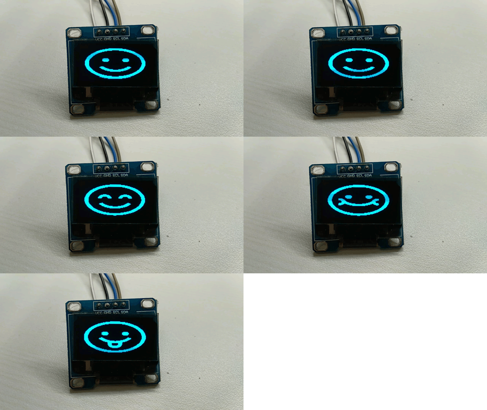
Output of 128x64 OLED Module using Arduino Uno
Components Used
Powered by
OLED (Organic Graphic Display) display modules are compact and have high contrast pixels which make this display easily readable. They do not require backlight since the display creates its own light. Hence they consume less power. It is widely used in Smartphones, Digital display.
485-938
Downloads
References
Comments10
Join the discussion — share a question or tip.
- JE
Hii I interface the OLED ( I2C IIC serial OLED Module) display to node MCU it was working but confused about how to print the data in particular place in OLED screen to display the IP_Adress on OLED screen please give solution to display wifi status on OLED Screen http://bigbelectronics.in/product.php?product=i2c-iic-serial-oled-lcd-led-module-0-96-inch-yellow-blue-12864-128x64-arduino-display-51-msp420-stim32-scr
- AA
Sir, how can we read data at particular cursor position of OLED. for eg. first I display "Eagle" on OLED then now i want to read this data character by character. Please help.....it's urgent.
- NE
Well, this is awkward! I changed the sketch to include Adafruit_SSD1306.h after making sure that the correct size display was enabled. It now works! I then compared that header file to Adafruit_SSD1306_64.h and my editor program reported no differences. Changing the sketch back to call Adafruit_SSD1306_64.h allowed it to work properly, too!
- NE
@abhijitp - Thanks for your quick responses. 1. Yes, the sketch includes the correct header file. If it did not the error message would have been shown. { #if (SSD1306_LCDHEIGHT != 64 ) } 2. The display is indeed a 128 X 64 display. 3. The {display.drawBitmap(0, 0, Smiley_<n>, 128, 64, WHITE)} statements are correct. 4. I connected up an Arduino UNO R3 with identical results. No warnings were issued by the IDE in either case. 5. The IDE reports "Global variables use 826 bytes (40%) of dynamic memory, leaving 1222 bytes for local variables. Maximum is 2048 bytes." I will try your suggestion about modifying the program to spoof a 32 line display.
- NE
I didn't mention the Arduino is an Arduino Nano clone. --Doug
- AB
The older Nano's used to have an ATmega168 if I am not wrong. The newer Nanos have an ATmega328P just as the UNOs. Just check which one you have. The older ones with ATmega168 have lesser SRAM (1kB as compared to 2kB on the UNOs and the newer Nanos). If the SRAM is 1kB, there is a possibility that the RAM usage is going beyond 70% (approximately) (the Adafruit graphic library consumes considerable amount of RAM) and the Nano is giving unpredictable behavior (If that is the case, after verifying the sketch, the IDE will give a warning message). You will have to switch to another Arduino with higher SRAM if this is the case.
- NE
I have this project half working--that is, only the top half of the graphic is displayed. The only real difference from the code as downloaded is that I have made a copy of the header file Adafruit_SSD1306.h and renamed the copy Adafruit_SSD1306_64.h after commenting out the incorrect display heights and activating the correct one. The incorrect half-image does fill up the entire display area of the display. What have I done wrong?
- AB
You have not mentioned the size of your display. Make sure that you know the exact size of the display that you are using, and that you have accordingly made modifications in the header file to select the correct display size. I see that you have created a copy of the file named Adafruit_SSD1306_64.h and made modifications in that file. Have you changed the header file name included in the main sketch? It might just be happening that you have made modifications in Adafruit_SSD1306_64.h, but the file included in the main sketch is still Adafruit_SSD1306.h and you have a copy of Adafruit_SSD1306.h in the library folder. Since you have named the header file as Adafruit_SSD1306_64.h, you think the display is 128x64. But only half the image is being displayed is what you are saying, so there might be a chance that the display actually is 128x32. So you could try making modifications for a display of size 128x32 and see if it works. If possible, download the codes again and try them without any modifications, and if you want to do any modifications, do it directly in the files downloaded. It might help narrow down the possibilities exactly where the problem is occurring. If none of the above mentioned work, provide more details if possible, and we could try to figure out what exactly the problem is.