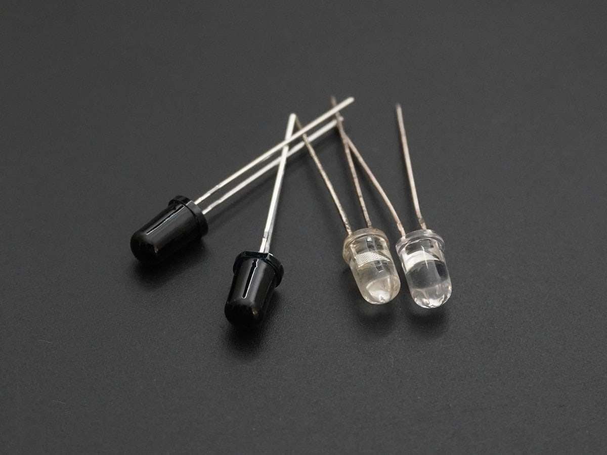
IR Communication using Arduino UNO
IR (infrared) communication is a wireless communication technology, used for short distance data/control transmission. It is commonly used in TV remotes, mobile phones, computers, and PDAs etc.
Overview of IR LEDs, IR Photodiodes, and TSOP1738
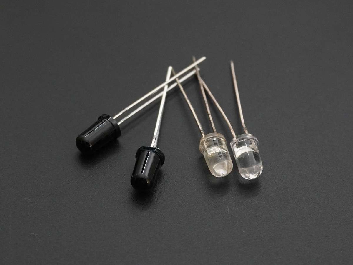
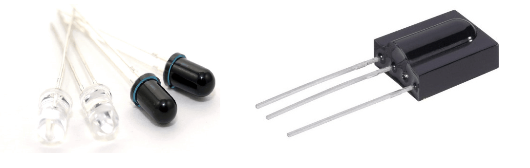
IR communication makes use of IR (Infrared) waves from the electromagnetic spectrum.
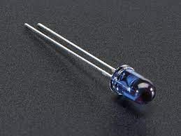
An IR LED is used to transmit data wirelessly in digital form (0 – LED OFF or 1 – LED ON).
An IR photodiode or IR phototransistor receives this data. The IR receiver (IR photodiode or IR phototransistor) gives different current values according to the intensity of light.
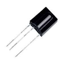
It is possible to modulate the data transmitted and there are special decoder IR receivers like TSOP1738 available that can receive the modulated data.
For more information about IR communication, refer the topic IR Communication in the sensors and modules section.
Connection Diagram for IR Communication using Photodiode and Arduino
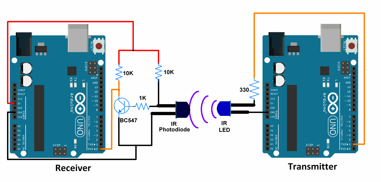
Note : In the diagram shown above, for the IR LED as well as IR photodiode, the longer lead is the Anode and the shorter lead is the Cathode.
Also, the Photodiode is used in the reverse biased mode (It is designed to operate in the reverse biased mode).
Connection Diagram for IR Communication using TSOP1738 and Arduino
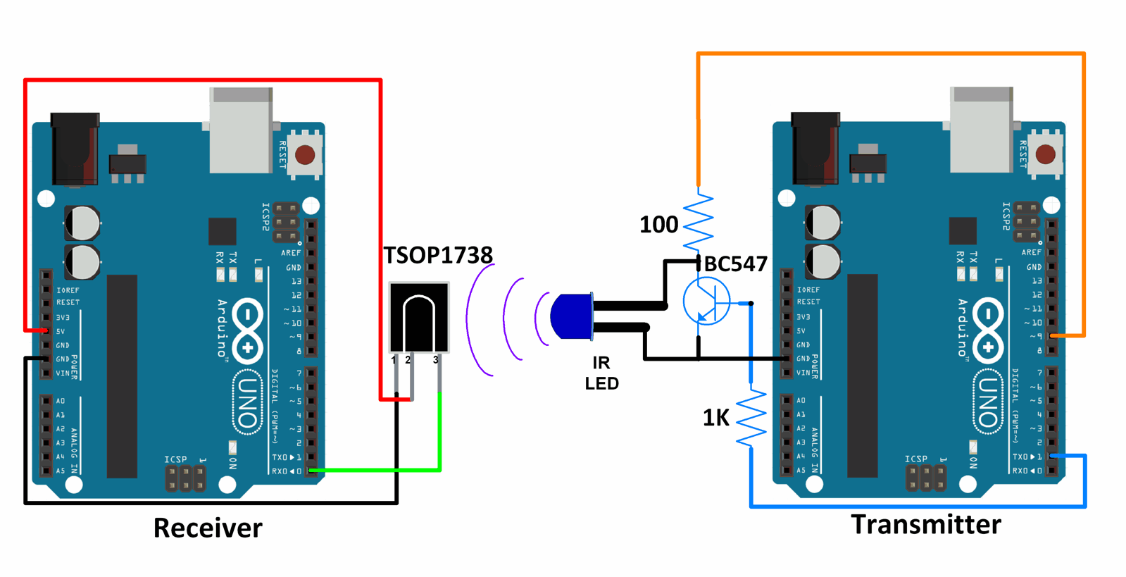
Note : In the diagram shown above, for the IR LED, the longer lead is the Anode and the shorter lead is the Cathode.
The data from transmitter side is modulated at 38 kHz before transmission.
The TSOP1738 is an IR Receiver with the capability to demodulate signals that have been modulated at a frequency of 38 kHz.
Any other TSOP17xx receiver like the TSOP1730 can also be used instead of TSOP1738. The only difference is the carrier frequency that it can demodulate. For example, TSOP1730 can demodulate signals that have carrier frequency 30 kHz. Corresponding changes in the modulation scheme need to be made at the transmitter side if TSOP1730 or some other receiver is used.
Example
Wireless IR communication between two Arduino Uno boards.
Here, a simple count is transmitted from the transmitter using IR LED. This count is received at the receiver by an IR photodiode or a TSOP1738. The count is transmitted as it is when the receiver is using IR photodiode. The count is modulated at 38 kHz when the receiver is using TSOP1738.
Note : IR is used just as a medium of data transmission between the transmitter and receiver. Data is being sent using USART protocol.
Word of Caution : In these example sketches, the Rx and Tx serial communication pins are being used. Arduino uses these pins while programming. Hence, we need to make sure that there is no external circuitry connected to the Rx and Tx pins while uploading the sketch. Failing to do this may result in error messages popping up while uploading the sketch. Once the sketch is uploaded, we can connect the externals circuitry to the Rx and Tx pins.
Code for IR Communication between IR LED And IR Photodiode Using Arduino Uno
Sketch for Transmitter
void setup() {
  Serial.begin(9600);	/* Define baud rate for serial communication */
}

void loop() {
  int count;
  for(count = 0; count<100; count++)
  {
    Serial.println(count);
    delay(1000);
  }
}
Sketch For Receiver
void setup() {
  Serial.begin(9600);	/* Define baud rate for serial communication */
}

void loop() {
if(Serial.available())	/* If data is available on serial port */
  {
    Serial.print(char(Serial.read()));	/* Print character received on to the serial monitor */
  }
}
Video of IR Communication using Photodiode and Arduino Uno
Code for IR Communication between IR LED And TSOP1738 using Arduino Uno
Sketch For Transmitter
#define cr_pin 9

void setup() {
  Serial.begin(1200);	/* Define baud rate for serial communication */
  tone(cr_pin, 38000);	/* For modulation at 38kHz */
}

void loop() {
  int count;
  for(count = 0; count<100; count++)
  {
    Serial.println(count);
    delay(1000);
  }
}
Sketch For Receiver
void setup() {
  Serial.begin(1200);	/* Define baud rate for serial communication */
}

void loop() {
if(Serial.available())	/* If data is available on serial port */
  {
    Serial.print(char(Serial.read()));	/* Print character received on to the serial monitor */
  }
}
Video of IR Communication using TSOP and Arduino Uno
Components Used
Powered by
Downloads
Comments27
Join the discussion — share a question or tip.
- MU
Can somebody help me? I tried both versions of the project and I'm only getting a reading using the TSOP1738 but even that output is coming in the form of inverted question marks. Please help.
- SH
Hi , I have a question. In the circuit which is using the TSOP reciever you used a transistor to run the IR led instead of directly running it via the arduino TX pin. Is is because the arduino TX pin cannot supply sufficient current to run the IR led ?
- LO
Replying to @komal
Means you want to use 3 transmitters and one receiver. At the receiver side, you want to know which transmitter transmits data and what data it transmits. As per their data you want to perform a specific task. correct? So, you have to use some set of rules while transmitting data and the same rule will need to apply at the receiver side. You need to encode the data while transmitting and at the receiver side, you need to decode data (pulses) for extracting information. This will help you to recognize which pulses (data) you are getting from which transmitter. Then, you can easily perform a required task.
- SH
Hi, thanks for sharing this project because im working on it too.. but, could you tell me the amplifier circuit for infrared communication using IR LED and IR photodiode to give a long distance communication (about 2 meters)? or how to change the baudrate for infrared communication using IR LED and TSOP 1738 from 1200 to 9600 baudrate?
- LO
Normal photodiode detects all ambient light. so it is sensitive to all nearby light which affects IR reception. You can use filtered IR photodiode which is sensitive for IR light only. May it will help to increase communication distance. Mostly, TSOP is used for long distance IR communication. you can refer circuit design for long distance communication using TSOP. http://www.electronicwings.com/avr-atmega/ir-communication-using-atmega1632
- AT
And no difference with another led
- AT
After more investigating, I tested out the tsop with my tv remote and saw voltage variations which is good but no reaction with my IR LED
- AT
Hi, I tried your project using TSOP2238 and Arduino pro Mini 3,3v (328p) but nothing happen. I tried your code, I tried to modify it but not results. The transmitter side looks like working because I can see the LEAD flashing with a camera but I don't how to verify the TSOP. Or is my Arduino in cause? Thanks for your help
- AB
@attsstudio: Hello, did you make connections properly for the TSOP2238? TSOP1738 and TSOP2238 are not pin-compatible. TSOP2238 has pin 1 as output, pin 2 as Vs, and pin 3 as GND. The pin connections could be a possible reason for not working. Another reason could be the baud rate. Use the same baud rate on the transmitter and receiver sides. Also, set the baud rate of the serial monitor of Arduino to the one you have used in the code.
- AT
Replying to @abhijitp
@abhijitp: Yes, same Baud rate and I used the connections in the doc of vishay (same as you said). But I had issues with serial, sometimes it sent only two characters on the monitor, I didn't know how I fixed it to be honest (I had to remove my leds with Digitalwrite, etc, but I don't understand why it interfered)
- AB
Replying to @attsstudio
@attsstudio: The wiring connection can pose a problem at times, Especially while using wires with female connectors. Breadboards can also be a problem at times if the contact is not made properly. If I am not wrong, your problem seems to be fixed. Is it working well now?
- AT
Replying to @abhijitp
@abhijitp: No sorry ^^ Serial monitor works but not the ir com. And wiring should not be a problem as everything is soldered.
- AB
Replying to @attsstudio
@attsstudio: I am not sure what could be going wrong then. I am pretty sure that you might have tried to rebuild the entire circuit many times, I suggest you give it one more try and build the circuit by looking at the diagram. On the transmitter side, there should be continuous printing on the serial monitor. This will happen irrespective of whether you have connected the IR LED or not. Make sure that the circuit on the transmitter is correctly built. Check the transistor you are using. It could be possible that the transistor is not working and hence you receive nothing on the receiver side. On the receiver side, data will be printed on the serial monitor only if the TSOP receives valid data. Is the TSOP in a working condition? If you have a spare, try replacing the one in your circuit. Maintain line of sight between transmitter and receiver. Lastly, you are using a Pro Mini. Make sure you are using the correct Rx and Tx pins. Try uploading the transmitter and receiver codes again. While uploading the codes, make sure there are no connections to the Rx and Tx pins of the Pro Mini. Once the codes are uploaded, connect the Rx and Tx pins.
- AT
Replying to @abhijitp
@abhijitp: I tried to rebuild the whole circuit for both sides but no change... But I have a question, is it normal if the TSOP voltage variations are only about 0.03 v?
- AT
Replying to @attsstudio
@abhijitp: To be honest, I tried a second time just now but no results. I tried the Photodiode way but it is too easy to interfere with, I've got results but easily bugged so I really want to use a TSOP. The part which sounds the more "error-sensitive" to me is the TSOP, can the 2238 (instead of the 1738) be the cause ? (What does the 17 or 22 mean by the way?)
- AB
Replying to @attsstudio
@attsstudio: I am not sure what could be going wrong to be honest. It could be possible that the Arduino Pro Mini you are using is Arduino Pro Mini 3.3V., and the circuit shown in the interfacing diagram requires 5V for correct operation. Maybe the BC547 does not get forward biased or something for the circuit (The circuit for TSOP, but might be working in case of circuit of photodiode) given at a voltage level of 3.3V. I would suggest you try substituting the Pro Mini with an UNO, or maybe a Pro Mini 5V (basically some Arduino with 5V). Or if you are good with transistors and their circuits, you could design the resistor values in the circuit for 3.3V (sorry I am unable to help you with that). Let me know if this solves your problem or not.