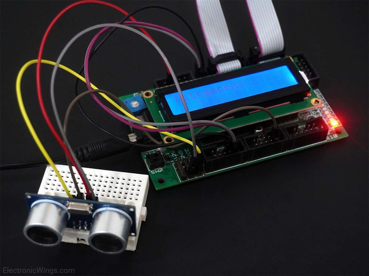
Ultrasonic Module HC-SR04 Interfacing with 8051
The ultrasonic module HC-SR04 is generally used for finding distance value and obstacle detection. It can operate in the range of 2-400cm.
Introduction
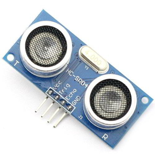
Ultrasonic HC-SR04 Module
Ultrasonic Module HC-SR04 works on the principle of SONAR and RADAR system.
- The HC-SR04 module has an ultrasonic transmitter, receiver, and control circuit on a single board.
- The module has only 4 pins, Vcc, Gnd, Trig, and Echo.
- When a pulse of 10µsec or more is given to the Trig pin, 8 pulses of 40 kHz are generated. After this, the Echo pin is made high by the control circuit in the module.
- The echo pin remains high till it gets the echo signal of the transmitted pulses back.
- The time for which the echo pin remains high, i.e. the width of the Echo pin gives the time taken for generated ultrasonic sound to travel towards the object and return.
- Using this time and the speed of sound in air, we can find the distance of the object using a simple formula for distance using speed and time.
For more information about ultrasonic module HC-SR04 and how to use it, refer to the topic Ultrasonic Module HC-SR04 in the sensors and modules section.
To measure time, we can use an in-built timer of 8051. To know about 8051 timers and their working, refer to topic 8051 timers in 8051 inside section
Interfacing Diagram
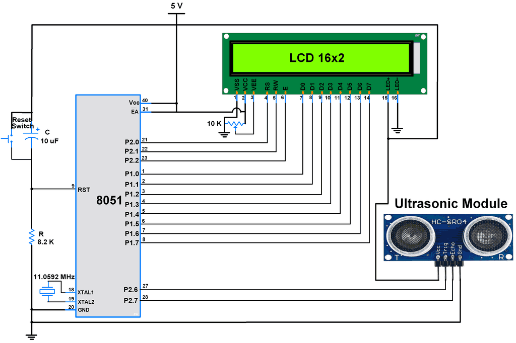
HC-SR04 Ultrasonic Module Interfacing with 8051
Example
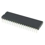
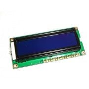
Here let’s design an application in which we will find a distance to an object by interfacing ultrasonic module HC-SR04 with 8051(here AT89S52 used) and display the distance on 16x2 LCD.
Steps of Programming
- 8051 microcontroller needs to transmit at least 10 us trigger pulse to the HC-SR04 Trig Pin.
- After getting a trigger pulse, HC-SR04 automatically sends eight 40 kHz sound waves and waits for rising edge output at the Echo pin.
- When the rising edge capture occurs at the Echo pin which is connected to the input of 8051, start Timer of 8051 and again wait for the falling edge on the Echo pin.
- As soon as the falling edge is captured at the Echo pin, the microcontroller reads the count of the Timer. This time count is used to calculate the distance to an object.
Calculation (distance in cm)
Where,
Sound Velocity = 34300 (in cm per second)
Here, the oscillator frequency of AT89S52 (8051) is 11.0592 MHz then the timer frequency of 8051 will be 921.6 kHz. So, the time required to execute 1 instruction is 1.085 us.
So, the timer gets incremented after 1.085 us time elapse.
e.g.
Program
/*
	Find distance of an Object by interfacing Ultrasonic HC-SR04 module with 8051(AT89S52)
	http://www.electronicwings.com
*/
#include<reg52.h>
#include <stdio.h>
#include <LCD_8_bit.h>
#include <math.h>

#define sound_velocity 34300  	/* sound velocity in cm per second */

#define period_in_us pow(10,-6)
#define Clock_period 1.085*period_in_us		/* period for clock cycle of 8051*/

sbit Trigger_pin=P2^6;        	/* Trigger pin */
sbit Echo_pin=P2^7;		/* Echo pin */

void Delay_us()
{
	TL0=0xF5;
	TH0=0xFF;
	TR0=1;
	while (TF0==0);
	TR0=0;
	TF0=0;
}

void init_timer(){
	TMOD=0x01;										/*initialize Timer*/
	TF0=0;
	TR0 = 0;
}

void send_trigger_pulse(){
	Trigger_pin= 1;           	/* pull trigger pin HIGH */
	Delay_us();               	/* provide 10uS Delay*/
	Trigger_pin = 0;          	/* pull trigger pin LOW*/
}

void main()
{
	float distance_measurement, value;
	unsigned char distance_in_cm[10];
	LCD_Init();			/* Initialize 16x2 LCD */
	LCD_String_xy(1,1,"Distance:");
	init_timer();			/* Initialize Timer*/

	while(1)
	{
		send_trigger_pulse();			/* send trigger pulse of 10us */

		while(!Echo_pin);           		/* Waiting for Echo */
		TR0 = 1;                    		/* Timer Starts */
    		while(Echo_pin && !TF0);    		/* Waiting for Echo goes LOW */
    		TR0 = 0;                    		/* Stop the timer */

		/* calculate distance using timer */
		value = Clock_period * sound_velocity;
		distance_measurement = (TL0|(TH0<<8));	/* read timer register for time count */
		distance_measurement = (distance_measurement*value)/2.0;  /* find distance(in cm) */

		sprintf(distance_in_cm, "%.2f", distance_measurement);
		LCD_String_xy(2,1,distance_in_cm);	/* show distance on 16x2 LCD */
		LCD_String("  cm  ");

		delay(100);
}
}
Video
Components Used
Powered by
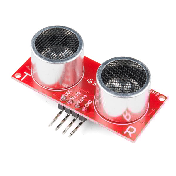
Ultrasonic module HC-SR04 is generally used for finding distance value and obstacle detection. It can operate in the range 2cm-400cm.
474-SEN-15569
Downloads
Comments10
Join the discussion — share a question or tip.
- RO
Can i get circuit connections I want to do a project on this as early as possible. Please send me at rohanshetty895@gmail.com
- YAyashcontractor31· edited
I open a source file in kail and open the project and create hax file and burn that GPS hax file into my controller But I don't get output on my LCD. Am i making any mistake in my program install/burn step ? Because I get output on Proteus simulator
- DA
Can you give me a hex file for 20x2LCD ? email:danny5522120@gmail.com
- SI
it's a built-in libraries in Keil Software
- PR
bro you send me requirement all componenet and fully circuit diagram prafulparel7789@gmail.com