NodeMCU SPI with Arduino IDE
NodeMCU based ESP8266 has SPI (Serial Peripheral Interface) feature. It is used to communicate with SPI enabled devices such as seven-segment displays, EEPROM, MMC and SDC memory cards, etc.
Introduction
The Serial Peripheral Interface (SPI) is a bus interface connection protocol originally started by Motorola Corp.
- SPI Interface uses four wires for communication. Hence it is also known as a four-wire serial communication protocol.
- SPI is a full-duplex master-slave communication protocol. This means that only a single master and a single slave can communicate on the interface bus at the same time.
- SPI enabled devices to work in two basic modes of SPI operation i.e. SPI Master Mode and SPI Slave Mode.
- The master Device is responsible for the initiation of communication. The master Device generates a Serial Clock for synchronous data transfer. Master Device can handle multiple slave devices on the bus by selecting them one by one.
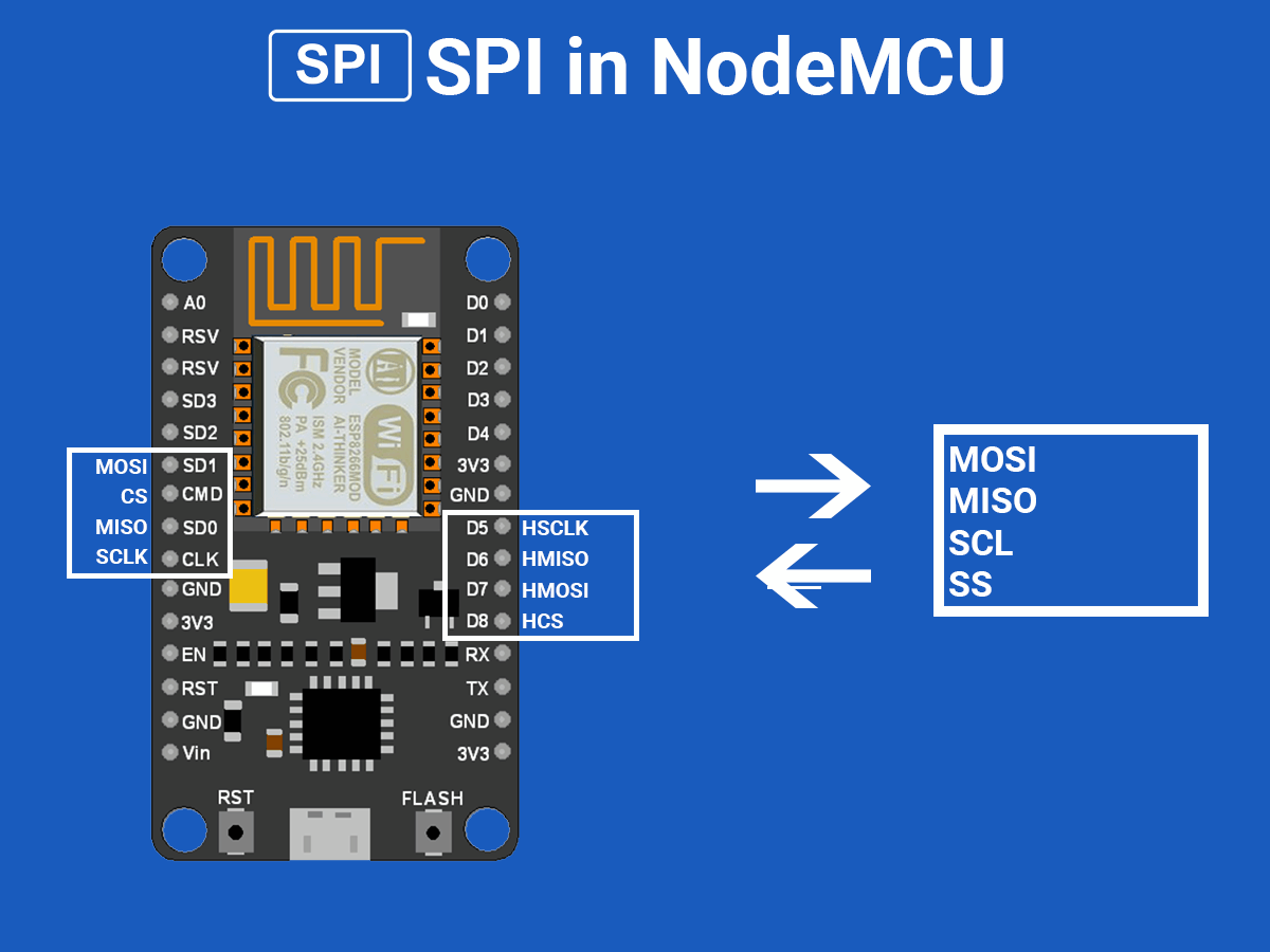
NodeMCU based ESP8266 has Hardware SPI with four pins available for SPI communication. With this SPI interface, we can connect any SPI enabled device with NodeMCU and make communication possible with it.
ESP8266 has SPI pins (SD1, CMD, SD0, CLK) which are exclusively used for Quad-SPI communication with flash memory on ESP-12E, hence, they can’t be used for SPI applications. We can use the Hardware SPI interface for user-end applications.
The below figure shows Quad SPI interface pins that are internally used for flash. It consists of quad i/o (4-bit data bus) i.e. four (SDIO_DATA0 – SDIO_DATA3) bidirectional (i/p and o/p) data signals with synchronizing clock (SDIO_CLK) and chip select pin (SDIO_CMD). It is mostly used to get more bandwidth/throughput than dual i/o (2-bit data bus) interface.
NodeMCU SPI Pinout
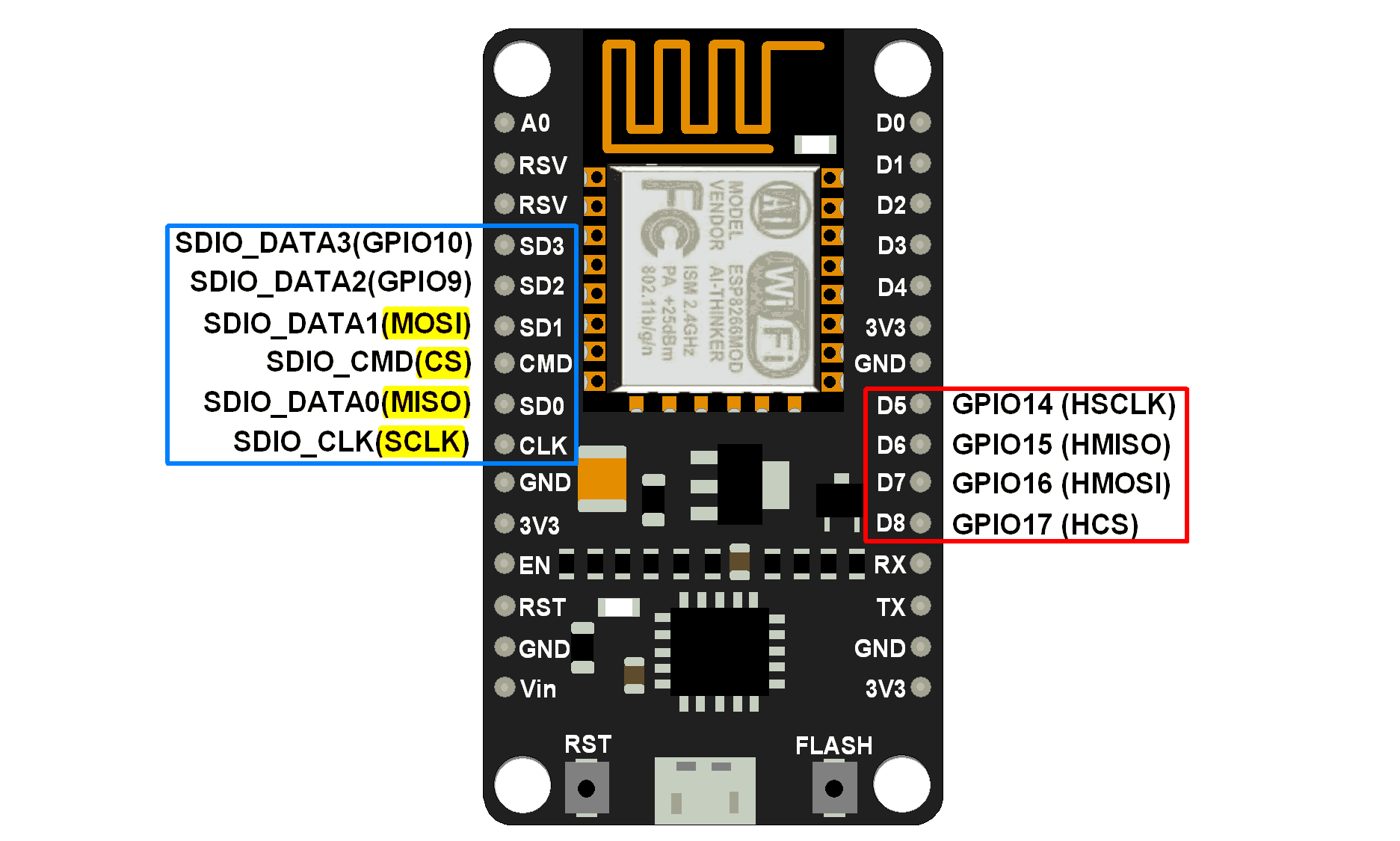
MISO (Master In Slave Out)
The Master receives data and the slave transmits data through this pin.
MOSI (Master Out Slave In)
The Master transmits data and the slave receives data through this pin.
SCLK (Serial Clock)
The Master generates this clock for communication, which is used by the slave.
Only the master can initiate a serial clock.
CS (Chip Select)
Master can select the slave device through this pin to start communication with it.
Example
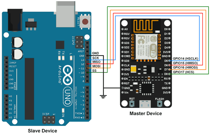
Let’s write an Arduino sketch of SPI communication for NodeMCU. Here NodeMCU is acting as a master device and we are using Arduino UNO as a slave device.
In this example, we are sending the “Hello Slave” string with ‘\n’ as the ending of the string from the NodeMCU Master device. The slave device receives this string and prints it on a serial monitor.
NodeMCU Master SPI Code using Arduino IDE
#include<SPI.h>

char buff[]="Hello Slave\n";

void setup() {
 	Serial.begin(9600); 	/* begin serial with 9600 baud */
 	SPI.begin();  			/* begin SPI */
}

void loop() {
	for(int i=0; i<sizeof buff; i++)  /* transfer buff data per second */
	SPI.transfer(buff[i]);
	delay(1000);
}
Arduino Uno Slave SPI Code
#include <SPI.h>

char buff [100];
volatile byte index;
volatile bool receivedone;  /* use reception complete flag */

void setup (void)
{
  Serial.begin (9600);
  SPCR |= bit(SPE);         /* Enable SPI */
  pinMode(MISO, OUTPUT);    /* Make MISO pin as OUTPUT */
  index = 0;
  receivedone = false;
  SPI.attachInterrupt();    /* Attach SPI interrupt */
}

void loop (void)
{
  if (receivedone)          /* Check and print received buffer if any */
  {
    buff[index] = 0;
    Serial.println(buff);
    index = 0;
    receivedone = false;
  }
}

// SPI interrupt routine
ISR (SPI_STC_vect)
{
  uint8_t oldsrg = SREG;
  cli();
  char c = SPDR;
  if (index <sizeof buff)
  {
    buff [index++] = c;
    if (c == '\n'){     /* Check for newline character as end of msg */
     receivedone = true;
    }
  }
  SREG = oldsrg;
}
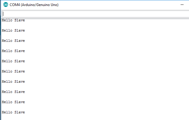
Slave Output Window
This output is received at the slave device which is transmitted from the master device.
Components Used
Powered by
Downloads
Comments20
Join the discussion — share a question or tip.
- AN
Sending back something from the slave device would be useful in an example like this. Like a "Hello Master" that the Node would then display on its Serial port since it is opened at 9600 baud. As a note, Arduino cannot nest interrupts so there is no need to protect yourself from another interrupt being called in the ISR routine.
- CU
Hi all, I tried the above code, there are no issues with uploading, but nothing is getting displayed on the Serial Monitor. I am using NodeMCU as the master, Arduino Uno as the slave device, baud rate of 9600, and the ground of both devices is common. I am not able to figure out the problem. Also i read on the arduino SPI reference page that <SPI.h> supports only Arduino as master. Wondering if that could be a problem? Any help would be appreciated. Thanks!
- CU
Changed the baud rate to 115200. It worked!
- RO
Have you found a solution?
- RE
Hi. Don't we need level shifters between arduino and nodemcu? Because Nodemcu works with 5V logic and nodemcu is 3.3V. like this one here: https://startingelectronics.org/tutorials/arduino/modules/pressure-sensor/#spi-uno
- RE
Replying to @lokeshc
I have read about this but I had some doubt because there is no confirmation in the datasheet.
- GE
i have a code error it says "'volatile byte index' redeclared as different kind of symbol" and if i change name from index to index1 i get this error "expected constructor, destructor, or type conversion before '(' token" in the " SPI interrupt routine", fixes needed, thanks
- SA
Replying to @lokeshc
can i use arduino nano with this arduino uno sketch as they both are boards of same family ? , if not what changes should i need to do in sketch to use arduino nano ble 33 as a slave? please help me i stuck at a very tight point thanks and regards from Zaid.
- AU
I think above spi example is better for your application. Also you can use i2c, uart communication in same
- AU
Replying to @ukay66
hello ukay, you can refer , https://github.com/esp8266/Arduino/issues/2134 where spi slave example discussed and merged for testing. also you can use other communication options (i2c, uart) for the same.
- MA
Hello, I have a problem. I uploaded both sketches to devices, and communication looks almost fine. In serial window in Arduino IDE, I can not see "Hello Slave", instead of this I see different chairs like this: "H%H$K S,A6A". Baud is set to 9600. Connection is right for sure. Every random words starts with "H" so, maybe I have a problem with looping somewhere. Please let me know if You have any suggestion, what should I change in my settings, I suppose it is only my problem if it works for You, and nobody else have problem. Thank You so much for the sketches, they are really helpful in my project.
- AU
Hello mac, make sure about common ground in your arduino and nodemcu communication, as in mostly cases this issue happens.