Frequency changing of pwm pins of arduino uno

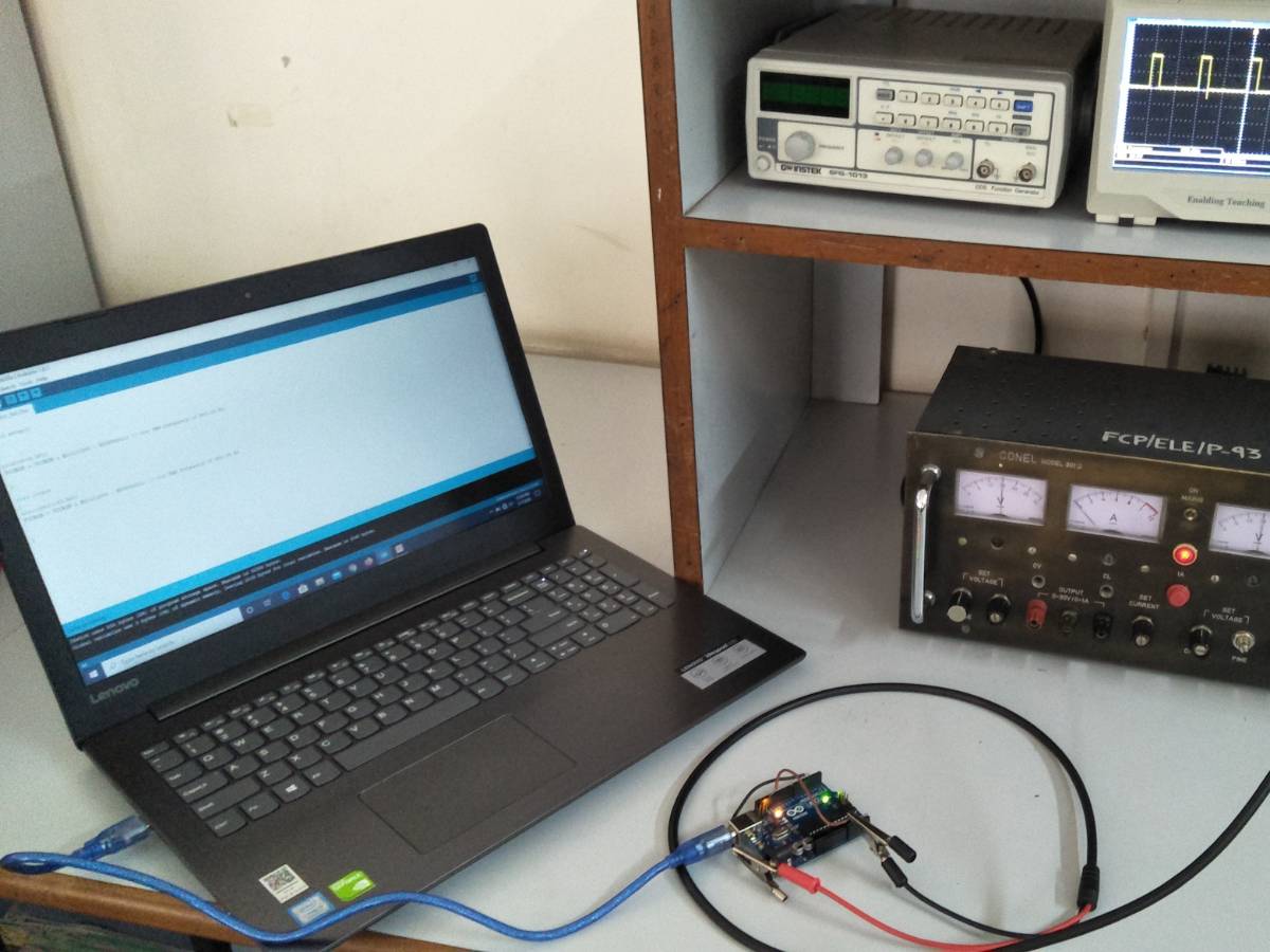
Components Used
Powered by
Benchtop Oscilloscopes 350 MHz 4Ch. with US Power Cord
372-DSOX3034G-USWW
As you all know " a story is made up of different chapter the chapter was completed by different different paragraph and the paragraph are made up of line which is made by words and its made by an alphabet "so its all started with small alphabet same like that we will start this by very small change in frequency of pwm pins of arduino uno.
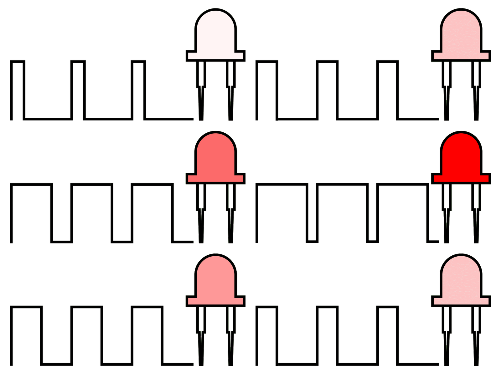
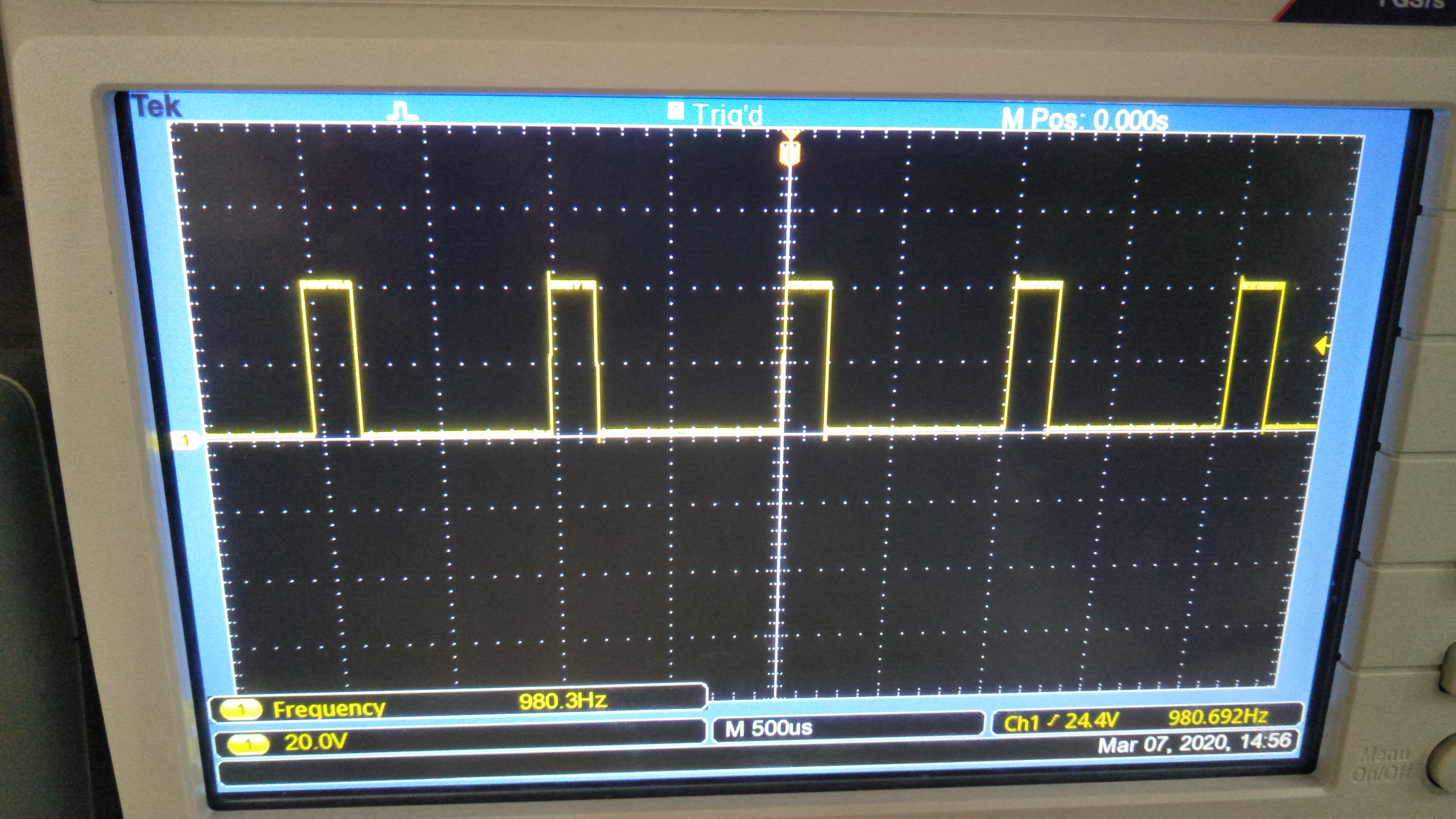
Note: If you observe carefully the Pulse High width is changing however, Pulse cycle duration (High + Low) is constant, i.e. frequency is constant.
ABSTRACT
Arduino Uno is the most popular Development board. It is widely used in building POC (Proof of concept) and prototypes. It is popular for beginner to learn. PWM (Pulse width modulation) is one of the most useful feature used in many applications. PWM is used by using function like "analog Write". With this function although width of the PWM cycle(Duty Cycle) can be changes but frequency remains constant. We can update this default Arduino PWM frequency to a value as high as 65Khz and as low as 30Hz by using a simple line of code”.
AIM :
To Change Frequency Of PWM Pins Of Arduino UNO.
OBJECTIVE
To study Aurduino UNO board.
To study PWM.
To study Proteus software.
To study digital oscilloscope(DSO).
Introduction
It follows logically that the frequency of the PWM signal is determined by the speed of the counter. Assuming you are using an UNO, this counter's clock is equal to the system clock divided by a prescaler value. The prescaler is a 3-bit value stored in the three least significant bits of the Timer/Counter register: CS02, CS01, and CS00.
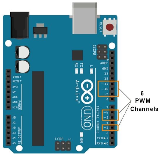
There are three such Timer/Counter registers: TCCR0B, TCCR1B, and TCCR2B.Since there are three different prescalers, the six PWM pins are broken up into three pairs, each pair having its own prescaler. For instance, Arduino pins 6 and 5 are both controlled by TCCR0B, so you can set Arduino pins 6 and 5 to output a PWM signal at one frequency. Arduino pins 9 and 10 are controlled by TCCR1B, so they can be set at a different frequency from pins 6 and 5. Arduino pins 11 and 3 are controlled by TCCR2B, so they may be set at a third frequency. But you can't set different frequencies for pins that are controlled by the sameprescaler (e.g. pins 6 and 5 must be at the same frequency).
If you use the default values set by the ArduinoDiecimila'sbootloader, these are your PWM frequencies:
Arduino Pins 5 and 6: 1kHz
Arduino Pins 9, 10, 11, and 3: 500Hz
How to change the PWM frequency
In the void setup() part of your Arduino code, set or clear the CS02,CS01, and CS00 bits in the relevant TCCRnB register.
For Arduino Uno, Nano, YourDuinoRoboRED, Mini Driver, Lilly Pad and any other board using ATmega 8, 168 or 328
PWM
Pulse Width Modulation or PWM is a method of Digital to Analog Conversion. It helps in delivering analog average voltage using digital pulses of variable pulse width. By controlling the on time and off time, we can generate an analog average voltage using the digital pulses.
PWM has a wide range of application. It is used in DC motor speed control, Brightness control of LED lamps etc.
Here in this simple experiment to understand the PWM working in ARDUINO, we read an analog input pin, maps the result to set the pulsewidth modulation (PWM) of an output pin. The input read from the analog pins will be in the range 0 to 1023. But the PWM fuction has a the width parameter ranging from 0 to 255, where 0 indicates fully off, and 255 indicates fully on pulses.
For better understanding and easy debugging, printing the results to the serial monitor is always performed.
map() is used to convert the the values ranging from 0-1023 to 0-255, which simplify the code and reduce the mathematical operations.
Pulse Width Modulation or PWM is a common technique used to vary the width of the pulses in a pulse-train. PWM has many applications such as controlling servos and speed controllers, limiting the effective power of motors and LEDs.
Basic Principle of PWM
Pulse width modulation is basically, a square wave with a varying high and low time. A basic PWM signal is shown in the following figure.
There are various terms associated with PWM −
On-Time − Duration of time signal is high.
Off-Time − Duration of time signal is low.
Period − It is represented as the sum of on-time and off-time of PWM signal.
Duty Cycle − It is represented as the percentage of time signal that remains on during the period of the PWM signal.
Period- As shown in the figure, Ton denotes the on-time and Toff denotes the off-time of signal. Period is the sum of both on and off times and is calculated as shown in the following equation −
$$T_{total} = T_{on}+T_{off}$$
Duty Cycle- Duty cycle is calculated as the on-time of the period of time. Using the period calculated above, duty cycle is calculated as −
$$D = \frac{T_{on}}{T_{on}+T_{off}} = \frac{T_{on}}{T_{total}}$$
analogWrite() Function
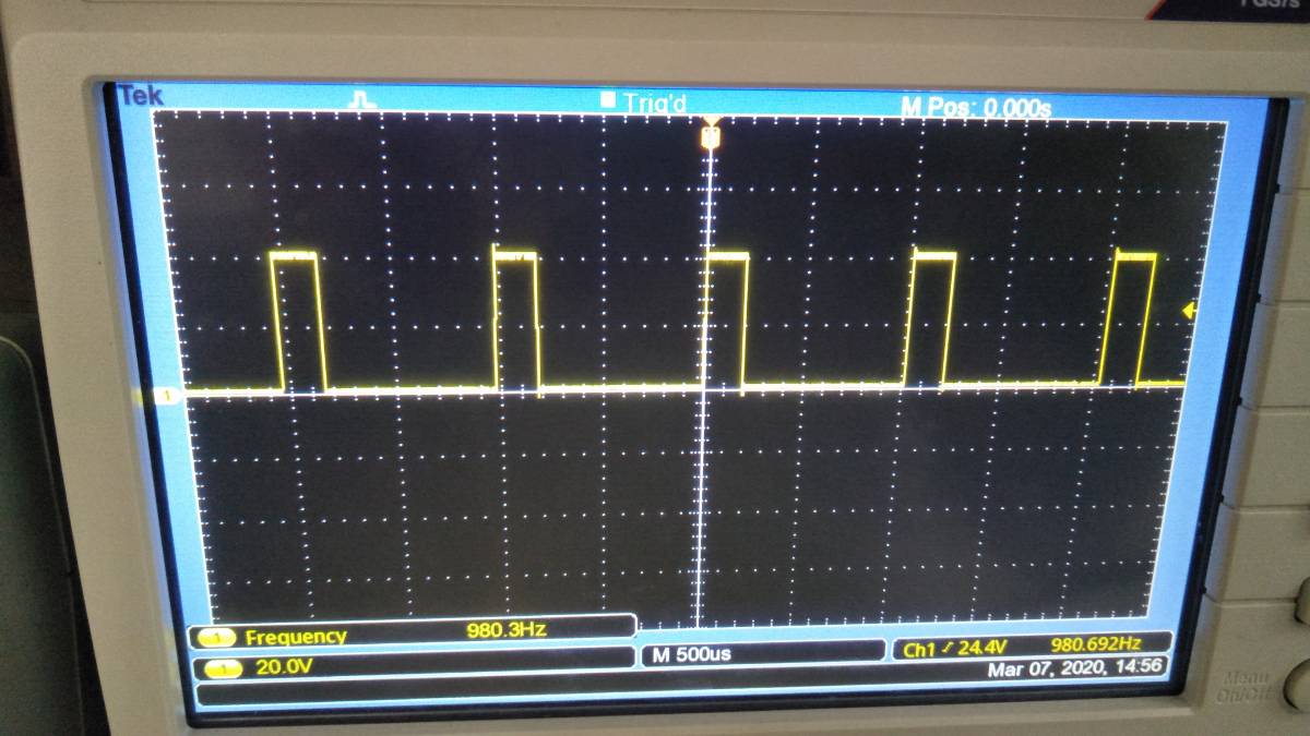
The analogWrite() function writes an analog value (PWM wave) to a pin. It can be used to light a LED at varying brightness or drive a motor at various speeds. After a call of the analogWrite() function, the pin will generate a steady square wave of the specified duty cycle until the next call to analogWrite() or a call to digitalRead() or digitalWrite() on the same pin. The frequency of the PWM signal on most pins is approximately 490 Hz. On the Uno and similar boards, pins 5 and 6 have a frequency of approximately 980 Hz. Pins 3 and 11 on the Leonardo also run at 980 Hz.
On most Arduino boards (those with the ATmega168 or ATmega328), this function works on pins 3, 5, 6, 9, 10, and 11. On the Arduino Mega, it works on pins 2 - 13 and 44 - 46. Older Arduino boards with an ATmega8 only support analogWrite() on pins 9, 10, and 11.
Circuit diagram & working
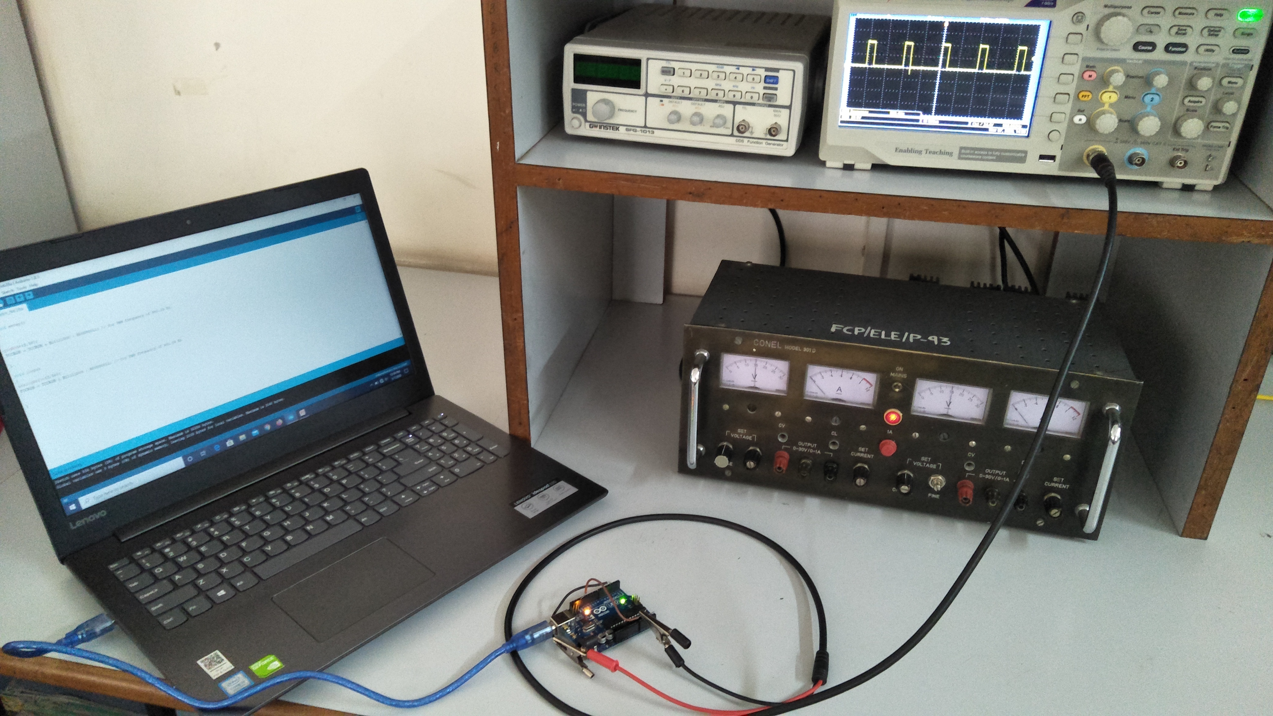
Circuit Connection
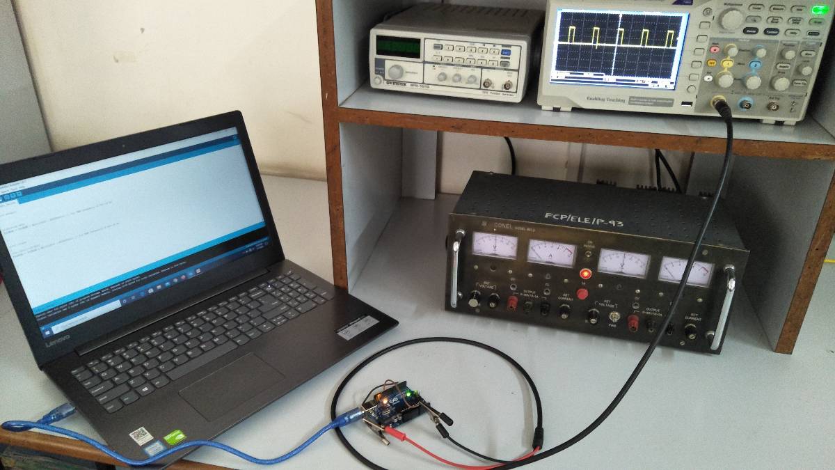
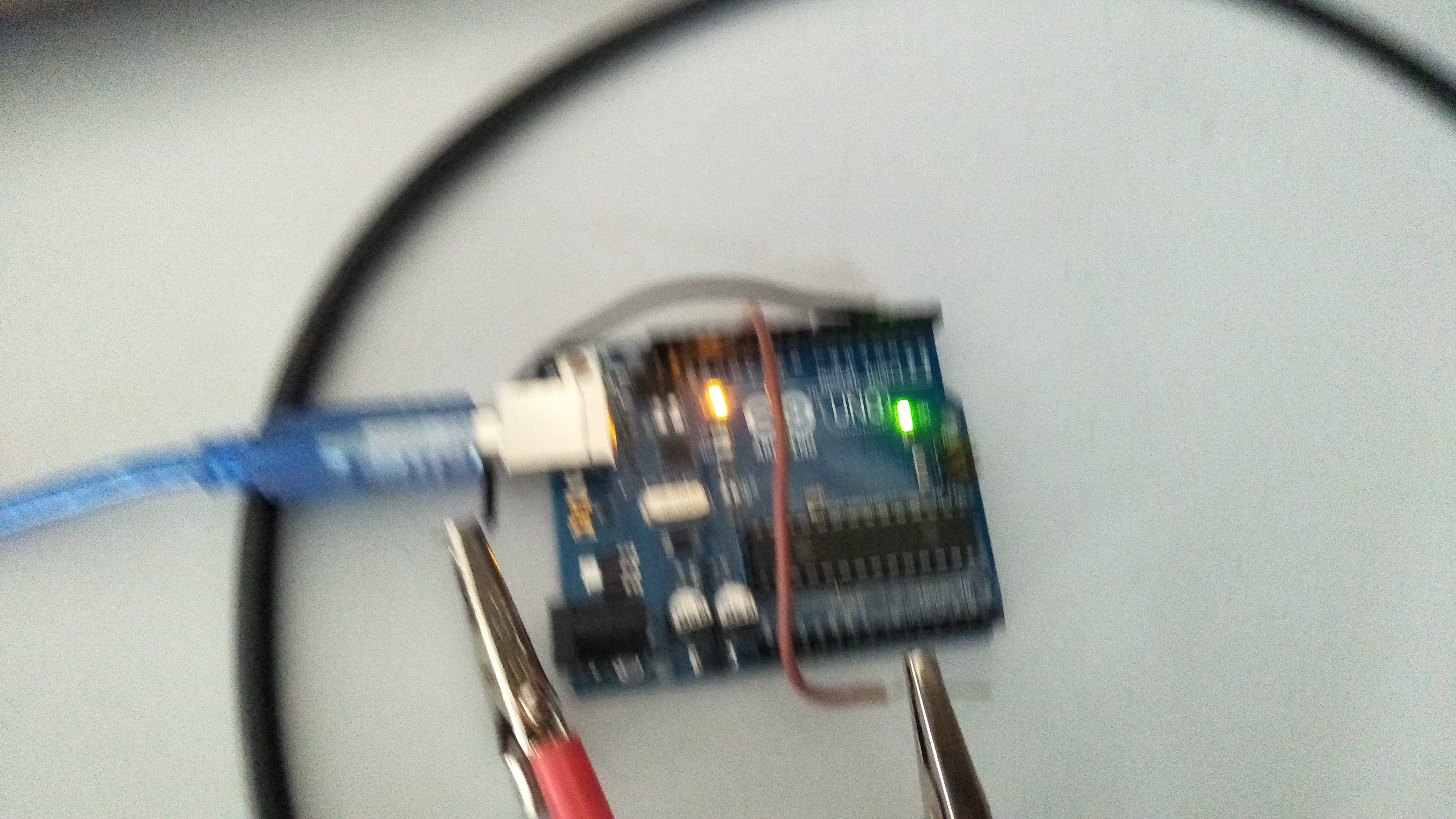
Connect Pin no 3 to DSO.
Working
- The Arduino IDE has a built in function “analogWrite()” which can be used to generate a PWM signal.
- The frequency of this generated signal for most pins will be about 490Hz and we can give the value from 0-255 using this function.
- analogWrite(0) means a signal of 0% duty cycle.
- analogWrite(127) means a signal of 50% duty cycle.
- analogWrite(255) means a signal of 100% duty cycle.
- On Arduino Uno, the PWM pins are 3, 5, 6, 9, 10 and 11. The frequency of PWM signal on pins 5 and 6 will be about 980Hz and on other pins will be 490Hz
Designing
Algorithm
- Start.
- Initialize the register.
- Display output.
- End.
Code
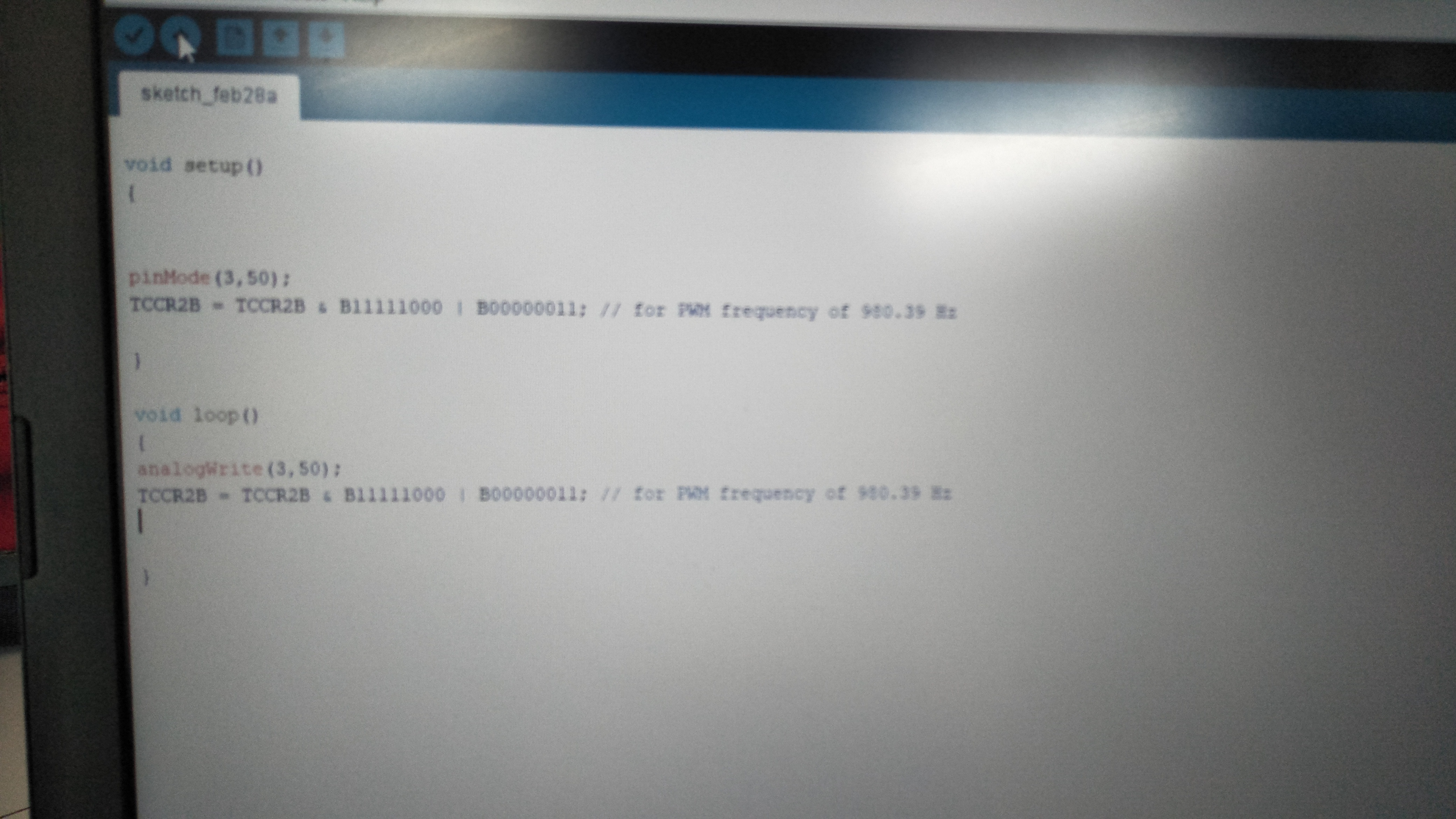
Program A – Default frequency on Pin 3
void setup()
{
    pinMode(3,155);
    TCCR2B = TCCR2B & B11111000 | B00000001; // for PWM frequency of 31372.55 Hz
}
void loop()
 {
    analogWrite(3,155);
    TCCR2B = TCCR2B & B11111000 | B00000001; // for PWM frequency of 31372.55 Hz
}
Program B – Changed frequency on Pin 3
void setup()
 {
    pinMode(3,155);
    TCCR2B = TCCR2B & B11111000 | B00000001; // for PWM frequency of 31372.55 Hz
}
void loop()
{
    analogWrite(3,155);
    TCCR2B = TCCR2B & B11111000 | B00000001; // for PWM frequency of 31372.55 Hz
}
Observation
PWM frequency for D3 & D11: 490.20 Hz (the default)
PWM frequency for D5 & D6: 976.56 Hz (the default)
PWM frequency for D9 & D10:490.20 Hz (the default)
Now, this frequency is not suitable in some applications, and there we might need to change the frequency.
Result & conclusion
With this simple code line, we can update the PWM frequency of Arduino.
Future scope
- It can be used for almost any application.
- One such application is in high-frequency circuits.
- Another example is SMPS
Downloads
Credits
Built by 2 contributors
Comments10
Join the discussion — share a question or tip.
For NANO TCCR0B = TCCR0B & B11111000 | B00000001; // 5 and 6 at 62.5 kHz or 977 Hz TCCR1B = TCCR1B & B11111000 | B00000001; // 10 and 9 at 31.3 kHz or 490 Hz TCCR2B = TCCR2B & B11111000 | B00000001; // 11 and 3 at 31.3 kHz or 490 Hz
I want frequency at 5khz. how can I achieve precisely that?. what is the logic for that?
You left out the one piece of information I was trying to find: how to set the pins to a desired frequency, say 120Hz.
Great work! Sir, I want frequency at 1.2kh how can I achieve precisely that? Thank you for your excellent work.
Hi! Should "TCCR2B = TCCR2B & B11111000 | B00000001; " mean highest possible frequency of 65khz as mention before?
No. They can't divide by zero. So if B000000 applied result will be division by one of the maximum frequency?
Ok. Wondering how to change to very low freq values like 10hz?
This is great! Thanks for documenting. May I suggest in setup put this: void setup() { TCCR0B = TCCR0B & B11111000 | B00000001; // PWM 31372.55 Hz pins 5 and 6 TCCR1B = TCCR1B & B11111000 | B00000001; // PWM 62745.10 Hz pins 9 and 10 TCCR2B = TCCR2B & B11111000 | B00000001; // PWM 31372.55 Hz pins 3 and 11 } Can you provide example of how to change those 1's and 0's to get different frequencies? It is not necessary to add anything in the main loop, just use the analogWrite as usual. When you change TCCR0B it will change the time of delay functions in your sketch. At 31372 Hz it will be 64 times faster. For a delay of 1 second you will need to do this: delay(64000)
great job guys..
What is the difference in Program-A and program-B?