Identify Colour of object using Colour Sensor

Components Used
Powered by
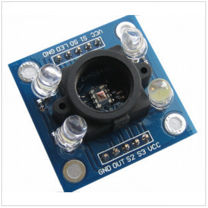
Color Sensor Module (TCS3200) can detect colors. It is generally used for color identification by their RGB values.
856-TCS3200D-TR
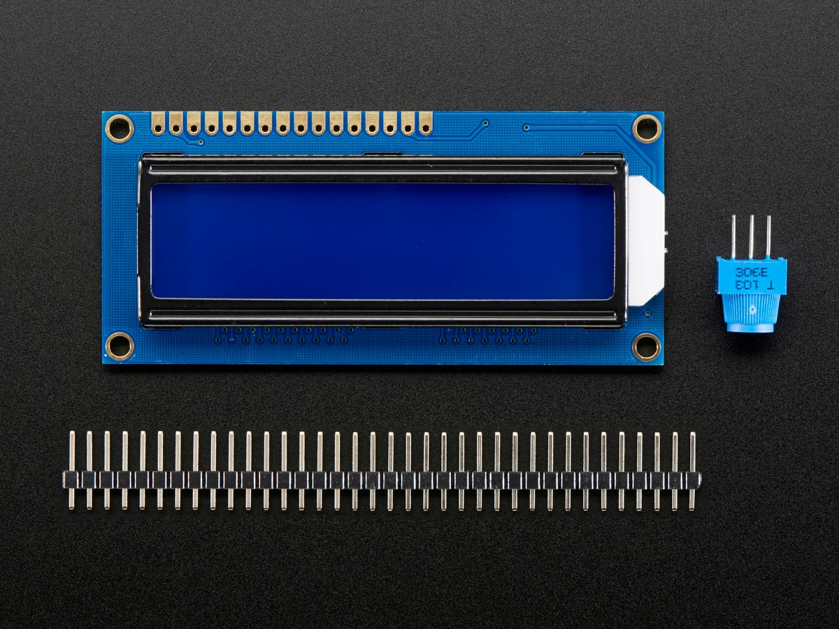
LCD16x2 has two lines with 16 character in each line. LCD16x2 is generally used for printing values and string in embedded application.
474-LCD-00255
Introduction
TCS3200 Colour Sensor
- TCS3200 is a color detector which is used to find or detect color of an object.
- It has TAOS TCS3200, 4 LEDs along with 8x8 array (R, G, B and clear) of photodiodes. This colour detector captures the colour of an object with the help of 8x8 array of photodiodes.
- Each 8x8 Red, Green, Blue photodiode array have Red, Green, Blue or clear (no) filter. These filters allow only one particular colour to pass and another colour will block. Then the current (I) output of these photodiode array is converted into frequency.
- This frequency output can be used by microcontroller to detect the RGB content of color or to find color.
- For more information refer TCS3200 Color Sensor Module
Programming Steps
To get the RGB values of colour,
1) Count the Frequency: At the start of program, it is required to count the frequency output given by Red pass filter, Blue pass filter and Green pass filter.
2) Convert Frequency value into RGB format: The RGB values are displayed in 0 to 255 ranges. So, It is necessary to map the frequency into RGB (0-255) value and will get RGB equivalent of the Red, Green and Blue pass filter output.
1) Count the Frequency
There are several methods to count/calculate the frequency. Here I am using Timer/ counter to count the frequency. The counter will count pulses for 100 ms and then multiply that count by 10 to get frequency count for 1 sec which is our frequency count.
unsigned long Frequency_Count(){
     unsigned long RGB_val;
     unsigned long count;
     unsigned int val;
     char value[10];
     TMR0 = 0;
     T0CONbits.TMR0ON=1;             /* turn ON timer */
     MSdelay(100);                   /* wait for 100ms to count frequency*/
     T0CONbits.TMR0ON=0;             /* turn OFF timer */
     count = TMR0;
     count = 10*(count + ((65536*overflow_count)));  /* if timer overflows then add that overflow count */
     overflow_count=0;
     return (count);
}
1) Convert Frequency value into RGB format
This Section is completely based on the object which is selected as a sample for colour detection. While sensing colour through sensor there should be take care with three things:
Frequency Mapping and White Balance
Mapping
- While counting frequency from Red pass filter, Green pass filter and Blue pass filter, it is necessary to map them in 0 to 255 range.
- While mapping frequency to RGB values, find maximum and minimum value for each color by taking sample on white and black color.
- When the color sensor put on White color it will give maximum frequency for R, G and B color.
- Whereas when the color sensor put on Black color then minimum frequency for each R, G and B color.
Formula
Mapped Value = 255*((Fo - Fd)/(Fw – Fd))
Where,
Fo – Output Frequency
Fd – Frequency of each color when expose to Black
Fw – Frequency of each color when expose on White
unsigned int Map_RGB(unsigned long min, unsigned long max,unsigned long count){
unsigned int val;
val = 255*(float)((float)(count - min)/(float)(max-min));
return val;
}
White Balancing
- White Balance means adjust a colour so that the colour of an object or image looks natural. It is necessary because most light sources do not emit purely white colour and have certain colour temperature. So to overcome this effect, we need to use white balancing of the colour.
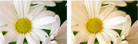
- In above fig, first image looks more natural than second image. White balancing is used on 1st image to look better.
- Here when we are finding color of an object, sensor output gives little darker color due to ambient light, reflection from an object, texture of an object. So to overcome this we can use white balancing to reduce this effect.
- Here, we increase the green content for white balancing which provide better results.
Note
- 1-3 cm distance between object and Sensor gives maximum frequency output.
- Colour output of sensor is dependent on texture, reflection property of object, surrounding light etc.
Color Identification using PIC18F4550 and Color Sensor
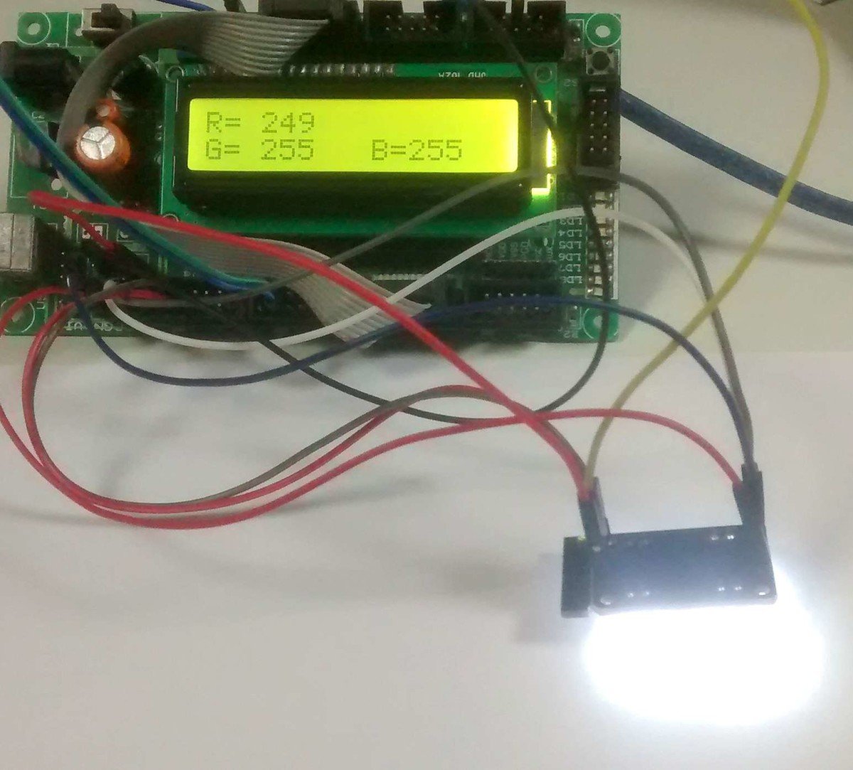
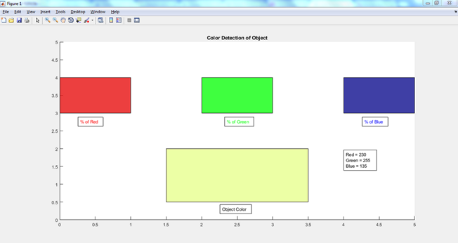
I interfaced Color Sensor TCS3200 with PIC18F4550 and display R, G and B content of an object on LCD16x2. Then I find RGB content of an object and send these values serially to the PC. By using Matlab, I find colour by mixing these RGB content. This colour is nothing but detected colour of an object.
Interfacing Diagram

Colour Sensor Interfacing with PIC18F4550 with LCD16x2
Create GUI using Matlab
I created a Matlab based GUI for indentifying color detected by TCS3200 color sensor. The program for PIC18F4550 reads the R, G and B content using TCS3200 and send these values serially to the Laptop.
Then on laptop matlab is used to read the R,G and B content and from that detected the color of an object. Refer display_color.m program for creating Matlab based GUI.
Output on Matlab
Video
Credits
Built by 1 contributor
Comments5
Join the discussion — share a question or tip.
Nice Work. I once wrote a program that tries to read a color from a gauge by extrapolating the RGB from the guage's picture on a computer screen. I like this concept better though as it doesn't require the computer.
hi iokehc nice project can saw your other project that detect white and black, im trying to replicate this one and covering also white and black is that possible?
Hie! I want a device to detect color of yarn and map that color to pre fed standard color chart . After mapping, I need it to display the no. Of shade from color chart. Can you help me in making that Or if possible, manufacture it for me. I would need them in 100s of pieces.
How can I contact you?
You can ask your query here. I will try to solve it.