Digital Readout Compass USing HMC5883L Magnetometer sensor
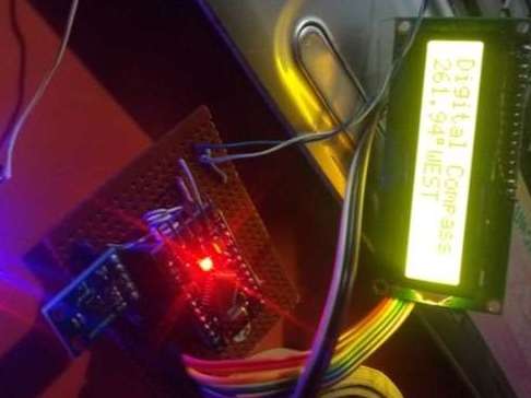
Components Used
Powered by
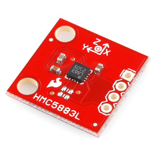
Magnetometer HMC5883L is developed by Honeywell. It gives the heading direction.
909-MOD-HMC5883L
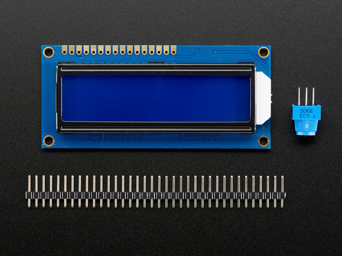
LCD16x2 has two lines with 16 character in each line. LCD16x2 is generally used for printing values and string in embedded application.
474-LCD-00255
Consumer Battery & Photo Battery 3.7V 2500mAh
406-ASR00050
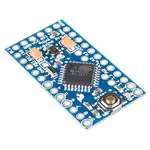
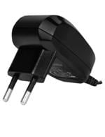
Wall Mount AC Adapters ac-dc, 5 Vdc, 2 A, SW, wall-plug, EU, P5 center pos, level VI, black
490-SWH15-5-EB-P5
Step 1:
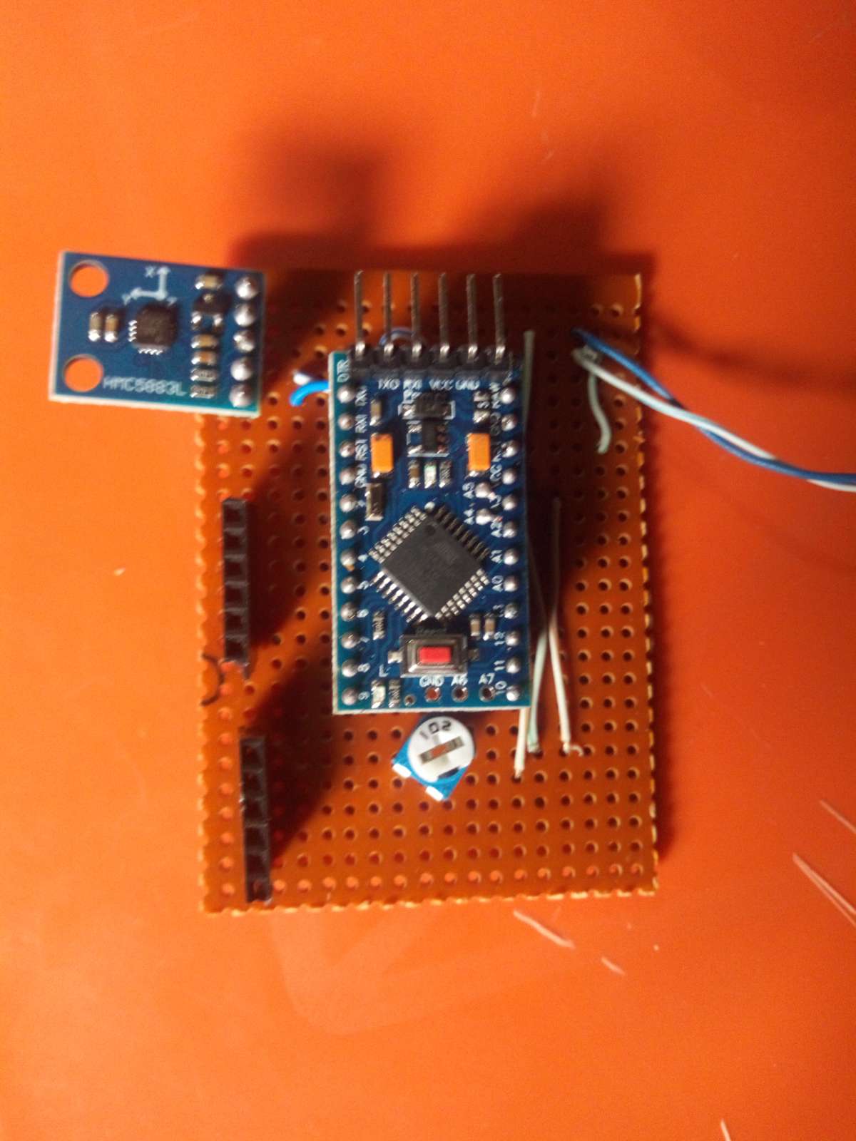
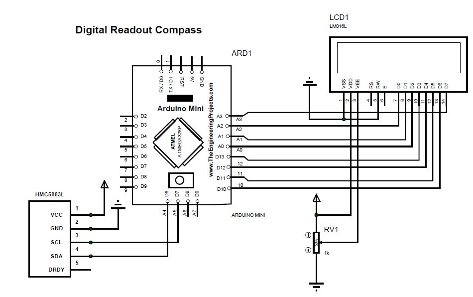
The various components to be used for the project were placed on the Vero board after the constructional diagram was prepared; the constructional diagram is the diagram that presents the actual look of the project on the board. And it formed the basis of the components placement which was achieved using the diagram.
Step 2:
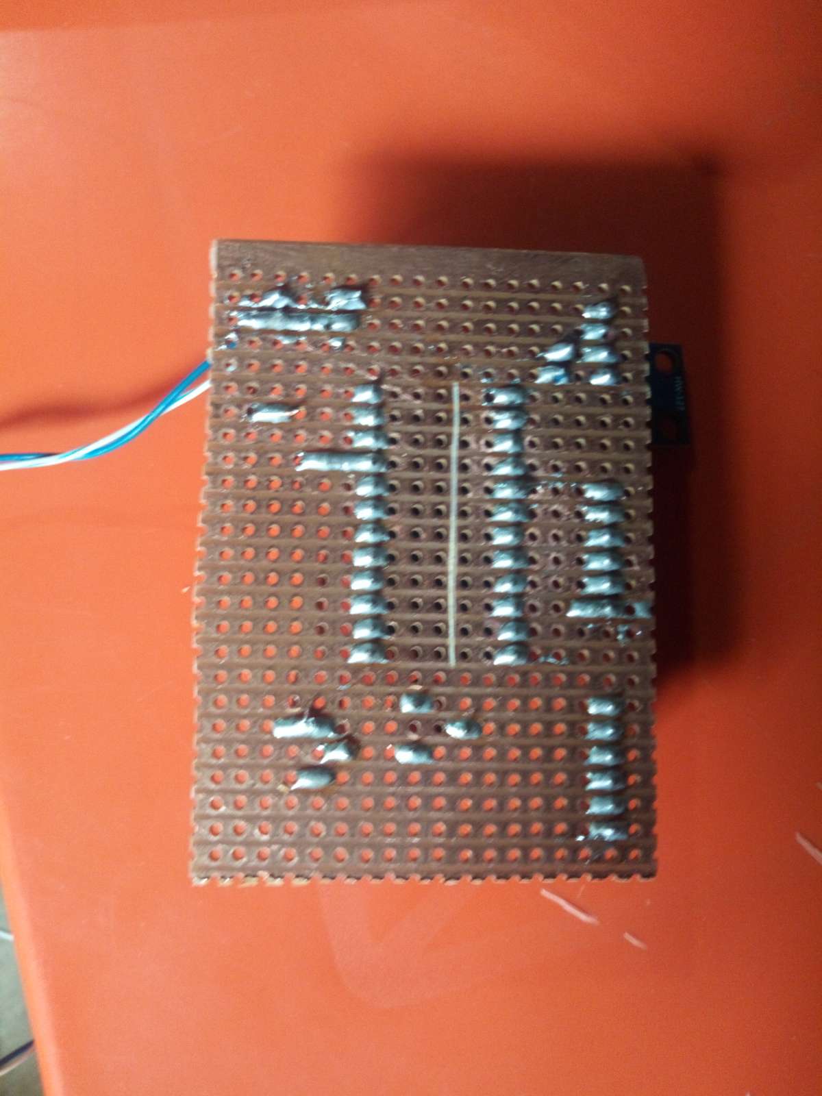
After the components have been placed on the Vero board, soldering of the components was carefully carried out using soldering tools which were soldering irons, the lead sucker, lead, soldering brush and cutter. The components were carefully soldered on the Vero board by applying the necessary soldering skills to ensure that the components were well soldered.
Step 3:
The Magnetometer sensor was calibrated using the declination calculator. Use of the declination calculator gave a simple and easy way to calculate up-to-date declination for any location on Earth by entering the Year, Latitude and Longitude of the location and the declination calculator will give the declination based on the latest magnetic reference field models.
Magnetic-declination site was also used to get the latitude, longitude and Magnetic declination of my location (Abuja Nigeria) and the compare the value gotten with the declination calculator value. Figure below shows the magnetic declination of Abuja, Nigeria.
.png)
Step 4:
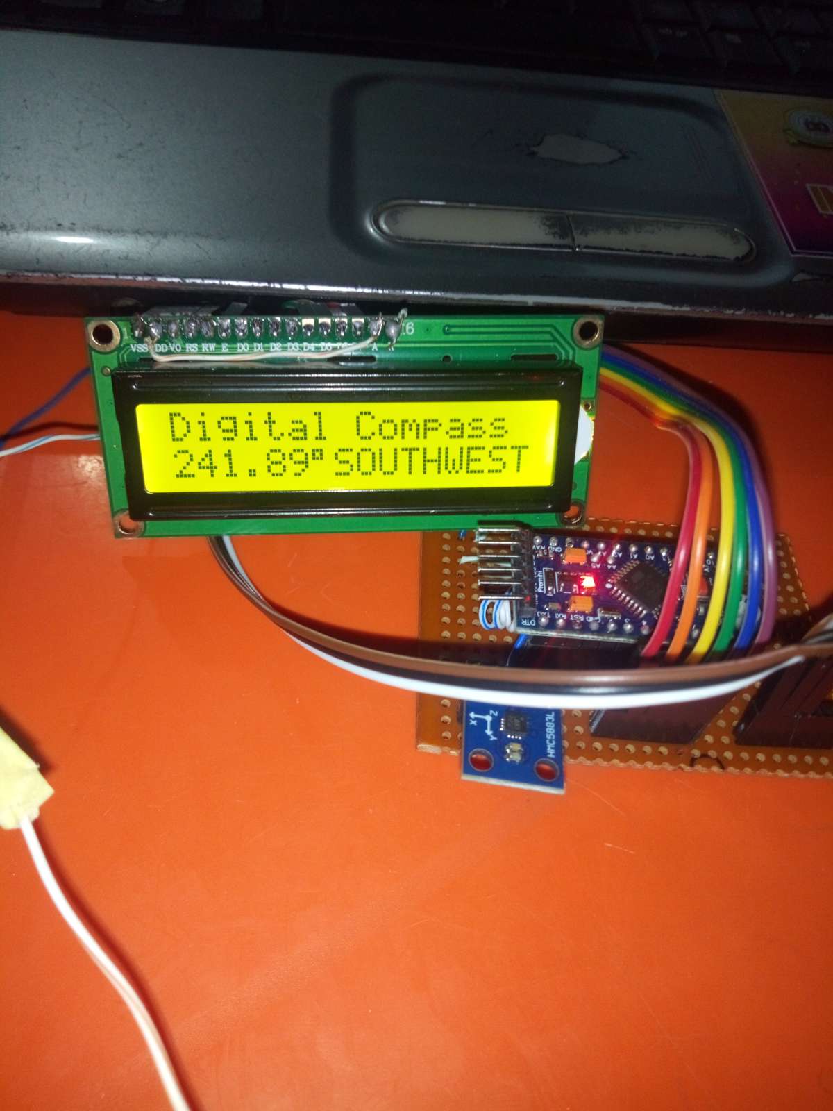
The circuit was tested after the completion of the soldering work. The hardware and software were integrated and the entire circuit was tested to verify if there was desirable output before casing the board.
Step 4:
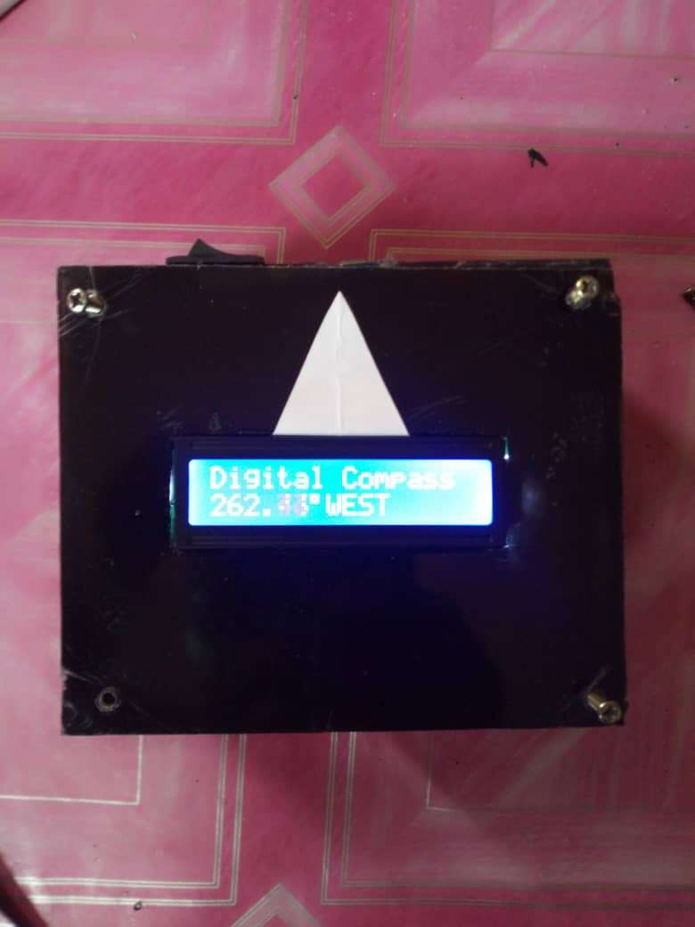
A plastic casing was made for this project after all the tests have been done. This was used to protect the circuit from being damaged and to make the whole project presentable and portable.
Credits
Built by 2 contributors
Comments0
Join the discussion — share a question or tip.
Be the first to share your thoughts on this project.